
Pointing device and method for determining rotational angle of pointing device

Inactive Publication Date: 2009-12-03
ASUSTEK COMPUTER INC
View PDF2 Cites 10 Cited by
  • Summary
  • Abstract
  • Description
  • Claims
  • Application Information

AI Technical Summary

Benefits of technology

[0016]The advantage of the invention is that, when the difference between the first rotational angle and the second rotational angle is too large, the pointing device calibrates the first rotational angle by the second rotational angle, and furthermore the resolution is raised.
[0017]The advantage and spirit of the invention may be understood by the following recitations together with the appended drawings.BRIEF DESCRIPTION OF THE APPENDED DRAWINGS
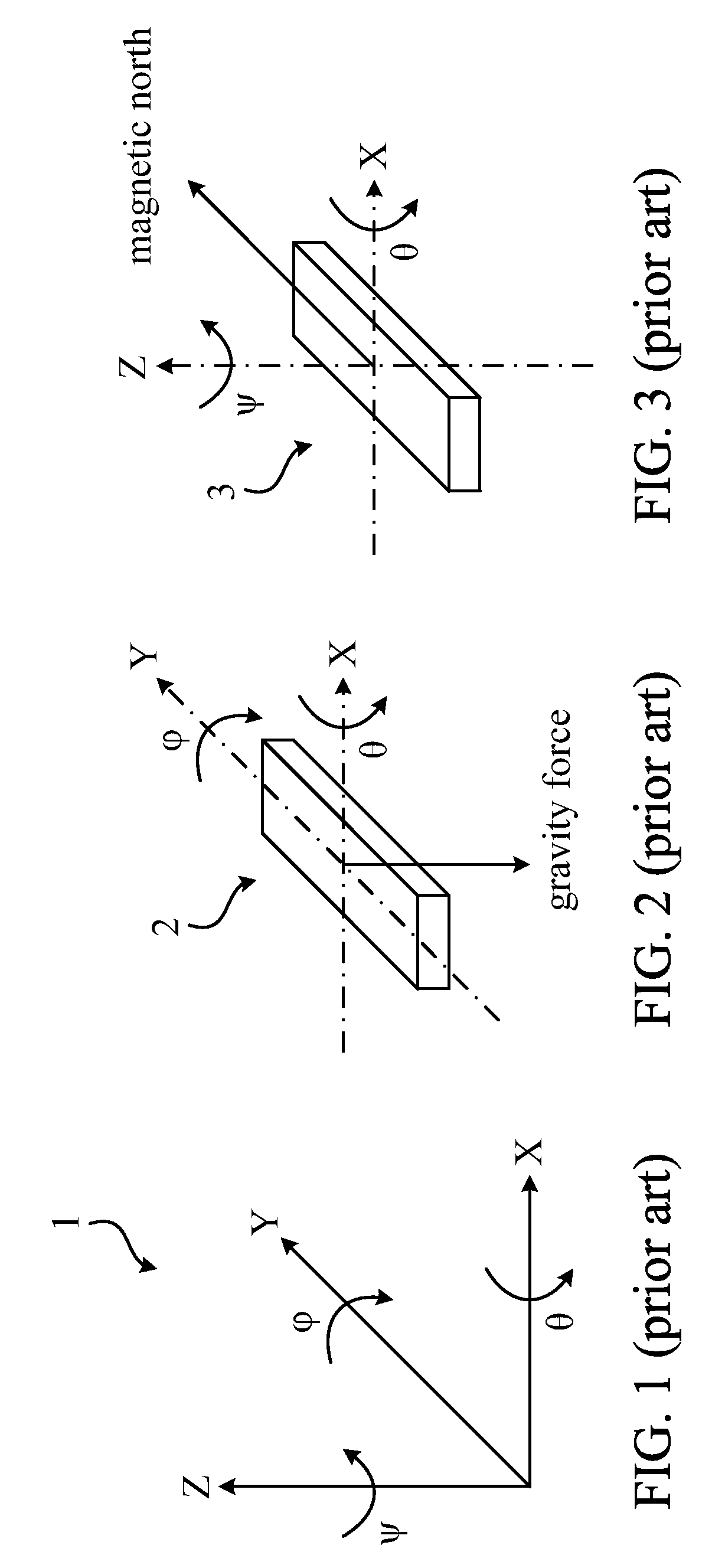
[0018]FIG. 1 is a schematic diagram illustrating an absolute coordinate system.
[0019]FIG. 2 is a schematic diagram illustrating a traditional G sensor for sensing a rotational angle.
[0020]FIG. 3 is a schematic diagram illustrating a traditional magnetic sensor for sensing a rotational angle.
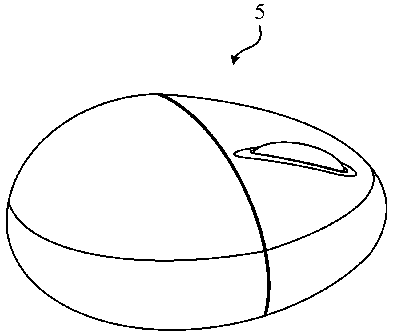
[0021]FIG. 4 is a schematic diagram illustrating a pointing device according to an

Problems solved by technology

Additionally, the G sensor and the magnetic sensor both naturally have electronic noise, and furthermore the positional accuracy is lowered.
The traditional 3D pointing device only adopts the signal outputted by a single sensing unit, and the traditional sensing unit such as a gyroscope, G sensor, and magnetic sensor has aforesaid disadvantages, so when a traditional 3D pointing device points at a single axis, the movement of the cursor can not be accurately controlled.

Method used


Image

  • Pointing device and method for determining rotational angle of pointing device
  • Pointing device and method for determining rotational angle of pointing device
  • Pointing device and method for determining rotational angle of pointing device

Examples


Embodiment Construction

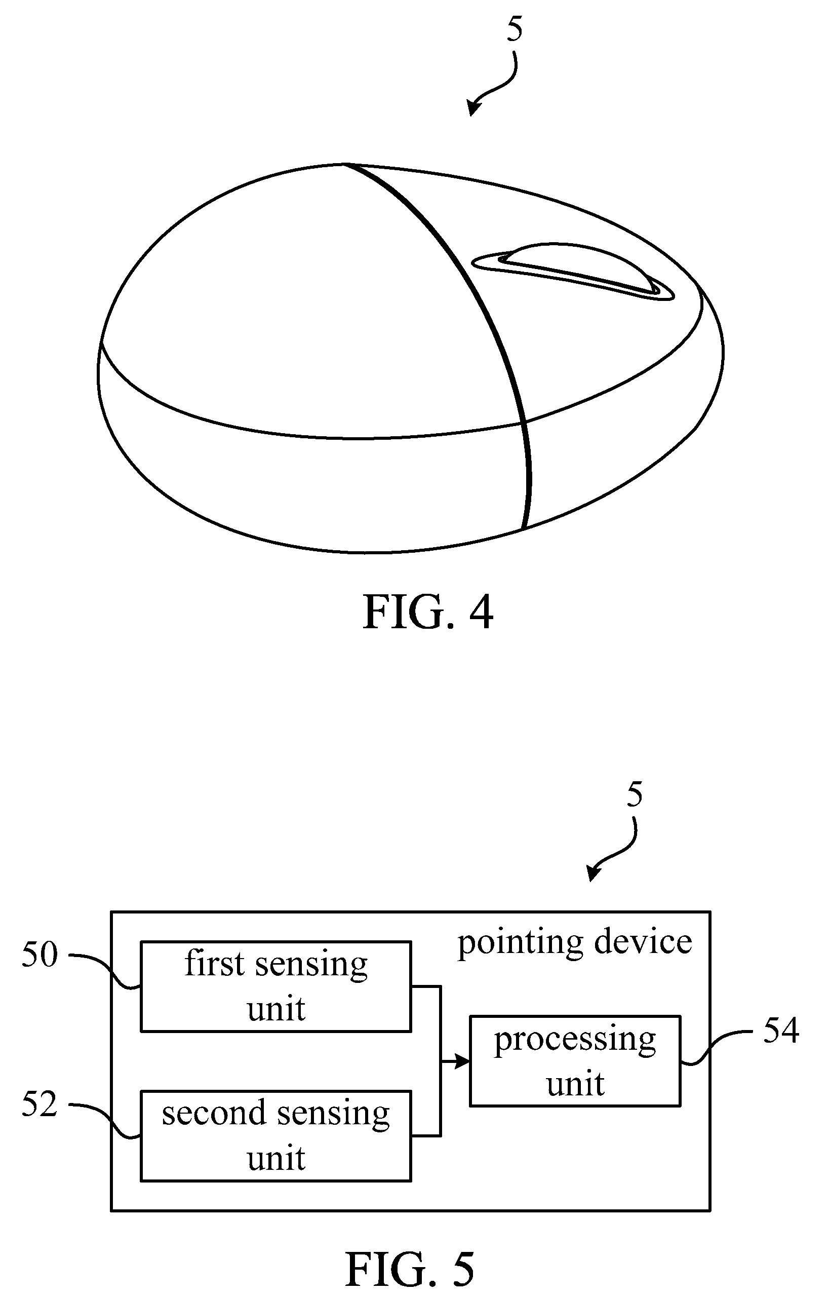
[0024]Please refer to FIG. 4 and FIG. 5. FIG. 4 is a schematic diagram illustrating a pointing device 5 according to an embodiment of the invention. FIG. 5 is a block function of the pointing device 5 shown in FIG. 4. Depending on practical application, the pointing device of the invention can be a mouse, a joystick, a trackball, etc. The pointing device 5 shown in FIG. 4 is, but not limited to, a mouse.

[0025]As shown in FIG. 5, the pointing device 5 includes a first sensing unit 50, a second sensing unit 52, and a processing unit 54. The first sensing unit 50 and the second sensing unit 52 are respectively coupled to the processing unit 54. In this embodiment, the first sensing unit 50 can be a gyroscope or other rotational sensing unit. The second sensing unit 52 can be a G sensor or a magnetic sensor.

[0026]When the user rotates the pointing device 5 to change the inclined angle, the first sensing unit 50 can sense the first rotational angle of the pointing device 5 relative to th...


PUM


Abstract

The invention discloses a pointing device comprising a first sensing unit, a second sensing unit and a processing unit. The first sensing unit is utilized for sensing a first rotational angle of the pointing device relative to an absolute coordinate system. The second sensing unit is utilized for sensing a second rotational angle of the pointing device relative to the absolute coordinate system. The processing unit is utilized for receiving the first and second rotational angles, calculating an absolute difference between the first and second rotational angles and judging whether the absolute difference is smaller than a predetermined threshold. If it is YES, the processing unit outputs the first rotational angle; otherwise, the processing unit calibrates the first rotational angle by the second rotational angle and then outputs the calibrated rotational angle.

Description

BACKGROUND OF THE INVENTION[0001]1. Field of the Invention[0002]The invention relates to a pointing device and particularly to a pointing device and a method for determining a rotational angle of the pointing device. The invention utilizes two sensing units to calculate and calibrate a rotational angle of the pointing device, and furthermore, the resolution of the pointing device is raised.[0003]2. Description of the Prior Art[0004]Presently, a computer is an electronic product for daily use. Generally, a user can utilize a keyboard and a pointing device such as mouse, joystick, touch panel, or track ball to input an instruction or further operate the computer to execute a particular function.[0005]To operate the pointing device in a space, the pointing device utilizes a sensing unit such as a gyroscope, G sensor, or magnetic sensor to sense a rotational angle. The main part of the gyroscope is a rotatable wheel posited on an axis. The gyroscope is designed for sensing and keeping d...

Claims


Application Information

Patent Timeline
IPC IPC(8): G06F15/00G06F3/033G06F3/0346G06F3/0354G06F3/038
CPCG06F3/0346G06F3/038G06F3/03543
Inventor HO, YUEH SHENG
Owner ASUSTEK COMPUTER INC
Learn More