Optical arrangement for a homing head with movable optical elements

Inactive Publication Date: 2007-05-08
DIEHL BGT DEFENCE GMBH & CO KG
View PDF12 Cites 4 Cited by
  • Summary
  • Abstract
  • Description
  • Claims
  • Application Information

AI Technical Summary

Benefits of technology

[0014]A further advantage of the invention is achieved when the control unit is prepared for controlling a sequence of tilt positions of the optical elements relative to one another in such a way that the object scene is imaged on the detector unit in multiple sequence—and in each case in a fashion offset from a basic image by less than one spacing between two adjacent pixels of the detector unit. A subpixel resolution can thereby be achieved with the aid of computational methods. The resolution can be raised to less than one pixel by summing up a number of images recorded in an offset fashion, and forming a centroid with the aid of image-processing methods. The summation can be built up such that a section of the image firstly comes to lie centrally on a pixel of the detector unit, and is deflected in subsequent images by a distance of in each case half the pixel pitch via the inactive zone between the pixels to the adjacent eight pixels, for example. The centroid of an object of the section can be calculated from the summed signal components.
[0015]In a further refinement of the invention, the arrangement comprises at least two pairs of optical elements each having one movement actuator, a first pair being provided for imaging a first section of the object scene, and a second pair being provided for imaging a second section, different from the first one, of the object scene on the detector unit. With the use of further optical elements, if appropriate, each pair therefore images a section of the object scene or a field of view on the detector unit, it being possible to compile the fields of view to form a total image. A large overall image of high resolution can be achieved.
[0016]The optical arrangement can be used in all target-tracking optics. A missile homing head having such an optical arrangement is particularly advantageous.

Problems solved by technology

The homing head is generally subjected in this case to shaking or vibrations which can render it difficult to evaluate the images recorded.
In addition, interfering radiation emitted for defensive purposes can render evaluation difficult.

Method used


Image

  • Optical arrangement for a homing head with movable optical elements
  • Optical arrangement for a homing head with movable optical elements
  • Optical arrangement for a homing head with movable optical elements

Examples


Embodiment Construction

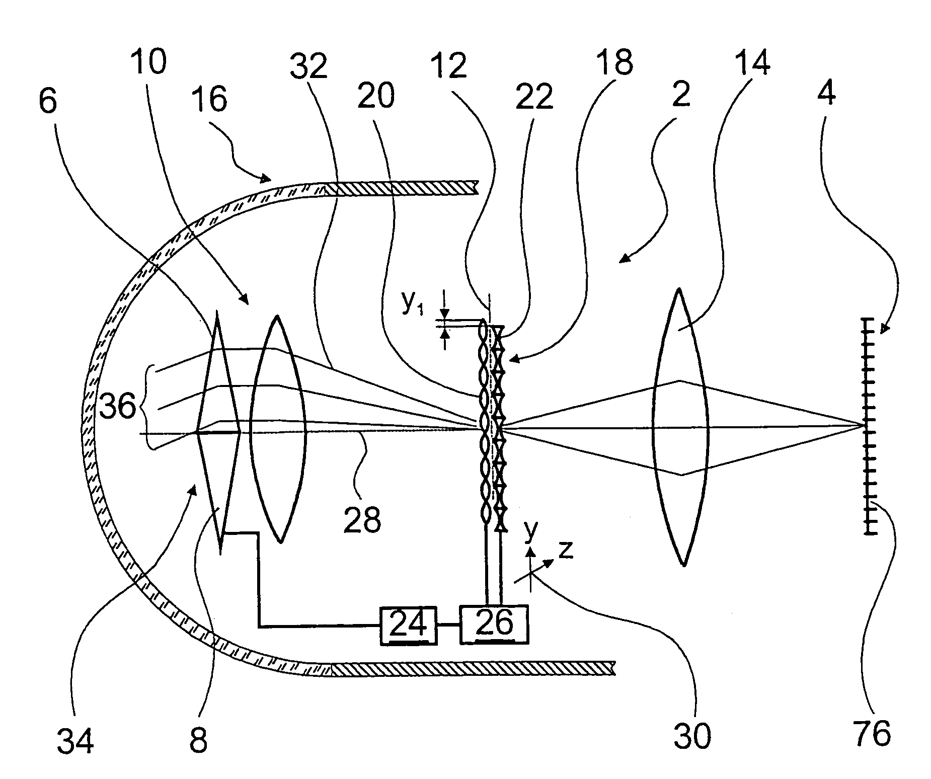
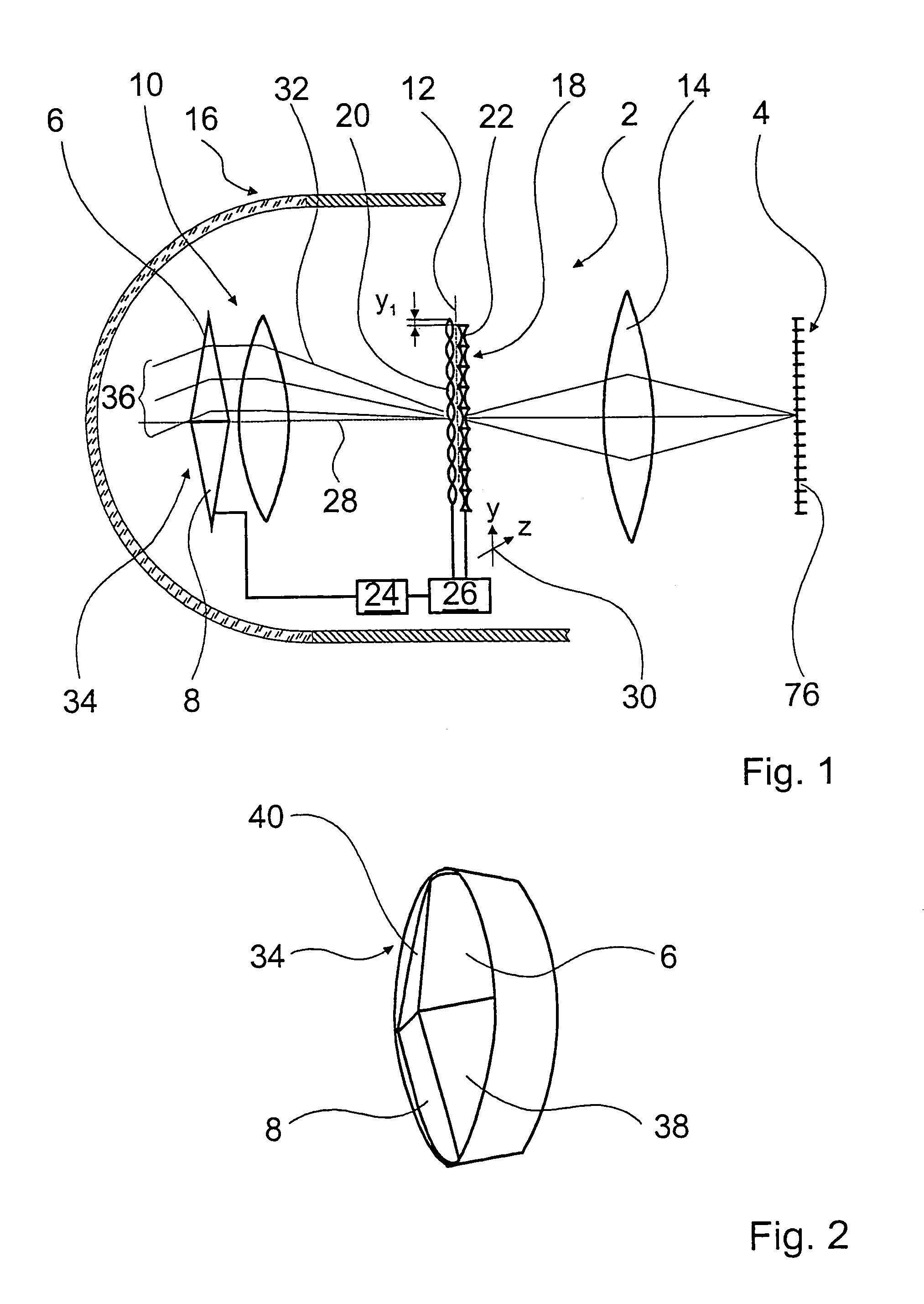
[0025]FIG. 1 shows an optical arrangement 2 for imaging an object scene onto a detector unit 4. The optical arrangement 2 comprises four prism pairs 6, 8, of which only two prism pairs 6, 8 are illustrated diagrammatically as triangles in FIG. 1. The four prism pairs 6, 8 are part of an optical unit 10 for directing radiation from four sections of the object scene in a superimposed fashion into an intermediate image plane 12 in which the four sections are imaged in a mutually overlapping fashion. Apart from the prism pairs 6, 8, the optical unit 10 is illustrated only diagrammatically as a lens. A second optical unit 14, likewise illustrated diagrammatically, serves the purpose of imaging the object scene on the detector unit 4. The optical arrangement 2 is arranged in a homing head 16 of a missile, whose casing is indicated.

[0026]A beam deflecting unit 18 having two microoptical lens fields 20, 22 is arranged in the intermediate image plane 12. The two lens fields 20, 22 comprise i...


PUM


Abstract

An optical arrangement (2) for a homing head (16), for the purpose of imaging an object scene onto a detector unit (4), including a control unit (24), a first optical unit (10) having two at least partially transparent optical elements, in particular prisms (42, 44), a second optical unit (14) and a beam deflecting unit (18), the first optical unit (10) directing radiation from at least two sections of the object scene onto the beam deflecting unit (18) in a superimposed fashion, and the beam deflecting unit (18) selecting one of the sections and, in conjunction with the second optical unit (14), imaging the selected section on the detector unit (4).

Description

BACKGROUND OF THE INVENTION[0001]1. Field of the Invention[0002]The invention proceeds from an optical arrangement for a homing head, for the purpose of imaging an object scene onto a detector unit, comprising a control unit, a first optical unit having two at least partially transparent optical elements, in particular prisms, a second optical unit and a beam deflecting unit, the first optical unit being prepared for directing radiation from at least two sections of the object scene onto the beam deflecting unit in a superimposed fashion, and the beam deflecting unit being prepared for selecting one of the sections and, in conjunction with the second optical unit, for imaging the selected section on the detector unit.[0003]2. Discussion of the Prior Art[0004]A target-tracking optics of a homing head, for example a missile homing head or a surface-based homing head, serves the purpose of imaging an object scene from the surroundings of the homing head with a high image refresh freque...

Claims


Application Information

Patent Timeline
IPC IPC(8): G01C21/02F41G7/22F41G7/26G01S3/781G02B26/08G02B26/10G02B27/64G05D1/12G05D3/20H01L27/00
CPCF41G7/2253F41G7/2293G02B26/0891G02B27/1066G02B27/1073G02B27/123G02B27/126G02B27/144G02B27/145G02B27/646H04N5/2254H04N5/2259G02B3/0062H04N23/58H04N23/55F41G7/2226G01S3/781
Inventor BAUMGART, JORGKROGMANN, DIRKTHOLL, HANS DIETER
Owner DIEHL BGT DEFENCE GMBH & CO KG
Why Eureka
Try Eureka