
Sensor system

a sensor and node technology, applied in the field of monitoring systems, can solve the problems of not being optimized for actual implementation, not being intended for nor optimized for use, and one sensor node cannot be reconfigured to perform as an alternative type of sensor node,

Active Publication Date: 2009-12-03
INT ELECTRONICS MACHINES
View PDF41 Cites 52 Cited by
  • Summary
  • Abstract
  • Description
  • Claims
  • Application Information

AI Technical Summary

Benefits of technology

[0018]The illustrative aspects of the invention are designed to solve one or more

Problems solved by technology

Even when two different sensor nodes incorporate overlapping functionality, one sensor node cannot be reconfigured to perform as an alternative type of sensor node.
However, the platform is much larger than a typical sensor node and is neither intended for nor optimized for actual implementations.
Similarly, the sensor nodes also are designed for a particular power source, and therefore cannot readily change from one type of power source to another.
Further, power consumption is frequently a limiting factor in the sampling and transmission rates for current sensor nodes.
In general, higher sampling and / or transmission rates require additional power consumption.
Because of the limited amount of available power in current sensor nodes, sampling and transmission rates are typically very low.
The transmission rate is also limited by the type of network in which sensor nodes are deployed.
In particular, most multiple sensor node networks are mesh networks, which generally cannot effectively use more than approximately twenty percent of their nominal bandwidth due to data collision resolution and data relaying requirements.
Various potential applications for sensor nodes also present unique challenges.
In this environment, various moving components make attachment and interrogation of the sensor nodes difficult.
Additionally, a large amount of vibration may be present, and high speed sampling is often desired.
Since many approaches fail to address all of these challenges, current practice requires schedule-based maintenance that includes regular inspections of all of the components of interest and components are often removed and discarded after a period of time and / or amount of usage, often well before the components have approached their true useful lifetime.
This situation poses a higher risk of injury to the inspectors / maintenance individuals, and costs billions of dollars annually.
Further, human observers / patrols and passive barriers (e.g., fencing) are often utilized due to the limitations of current sensor-based approaches.
The continued use of human observers / patrols results in limited monitoring, which also is extremely expensive.
However, these approaches nearly always use wired sensors.
The current approaches rely on individual compliance, which can increase a likelihood of injuries, and result in lost work, production, and operational times.

Method used


Image

  • Sensor system
  • Sensor system
  • Sensor system

Examples


Embodiment Construction

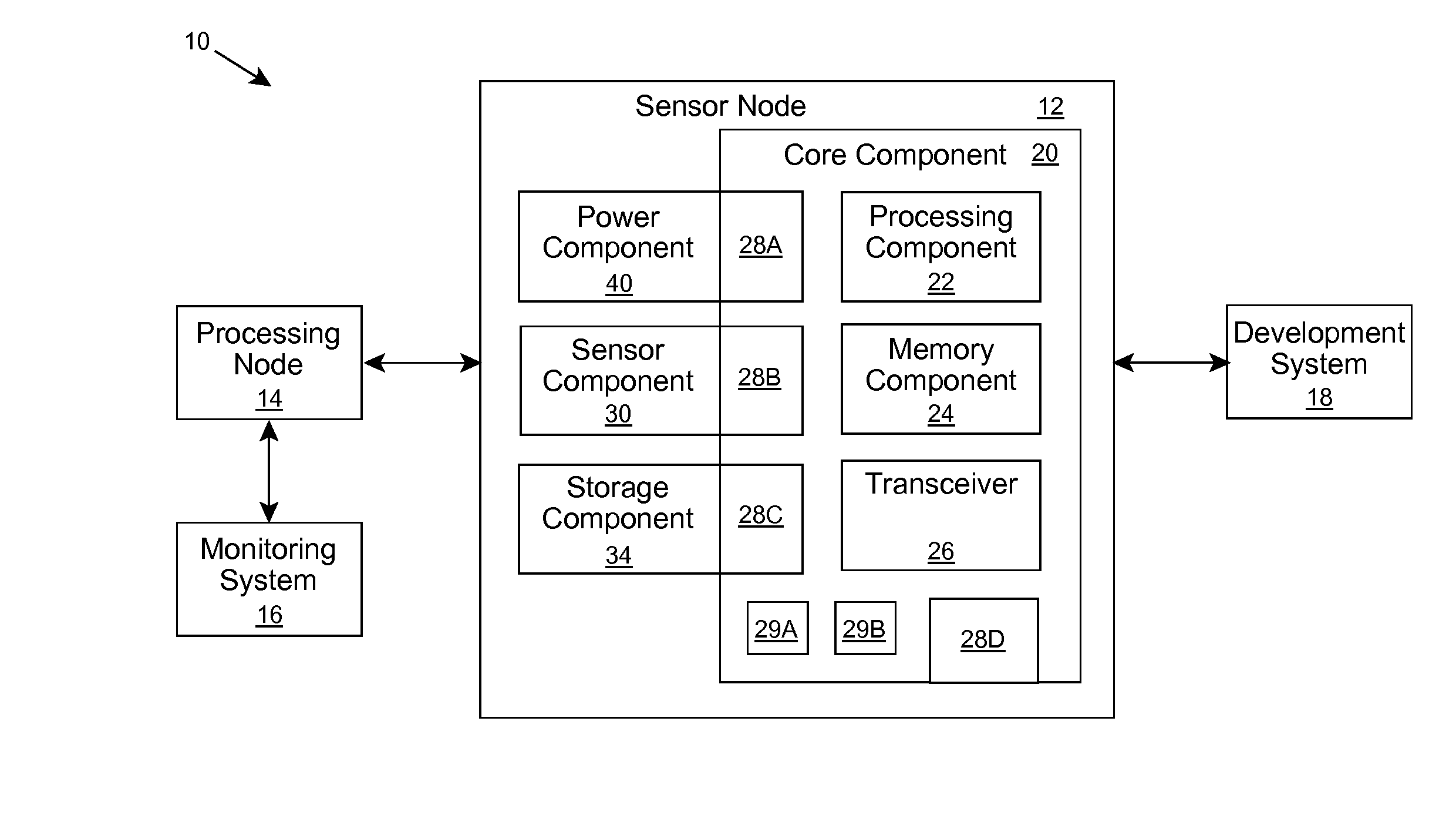
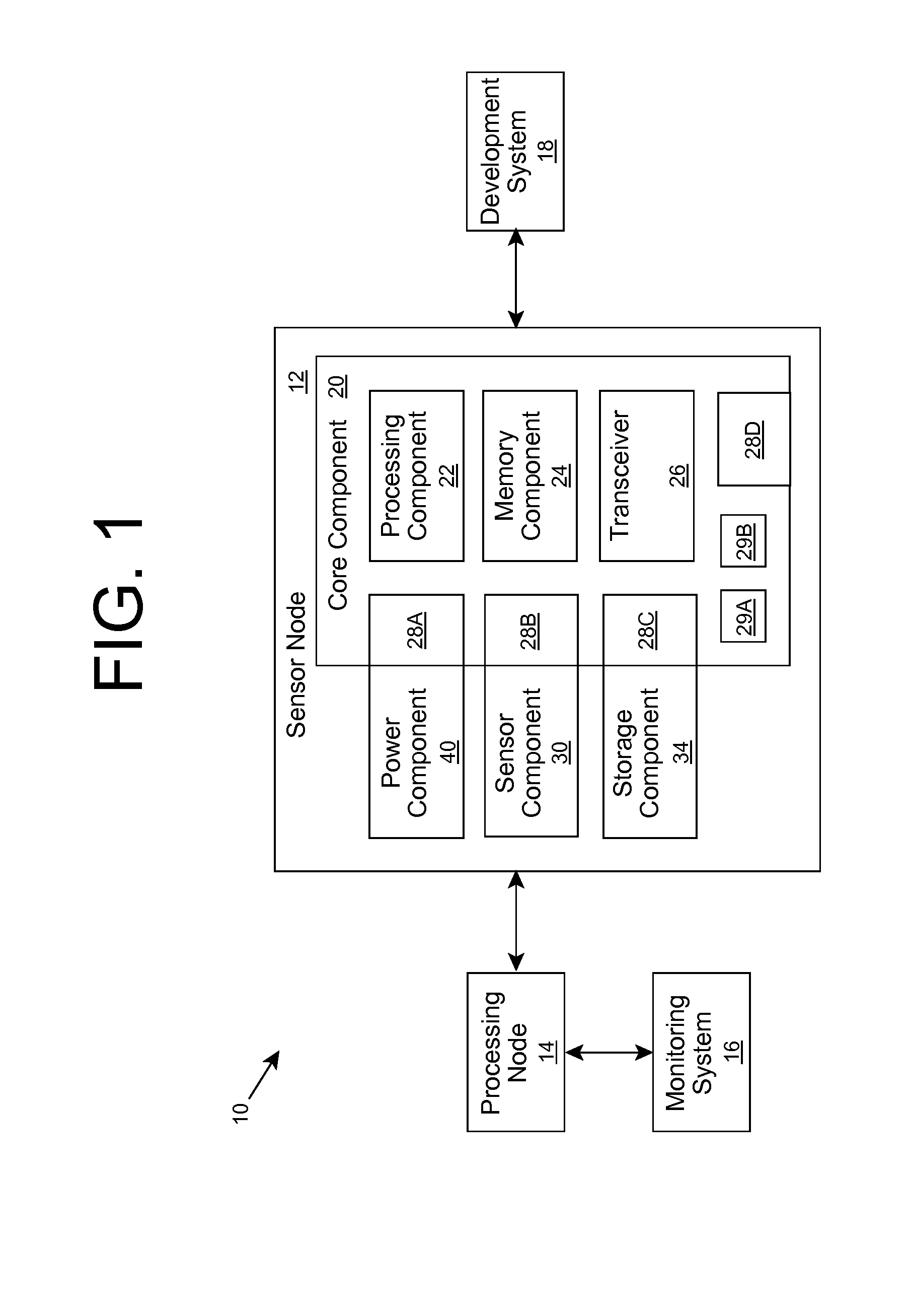
[0030]The inventors recognize that current sensor node designs can be improved. In particular, current sensor node designs are inflexible due to their requirements for re-design for each new application and / or power source that is desired. Further, current sensor nodes are not capable of being deployed for applications that require high sampling rates and / or high transmission rates. Still further, current power requirements of sensor nodes results in an inability to perform independently (e.g., using a battery and / or power harvesting device) without a disproportionately large battery and / or power harvesting device (e.g., several times the volume of the sensing device).

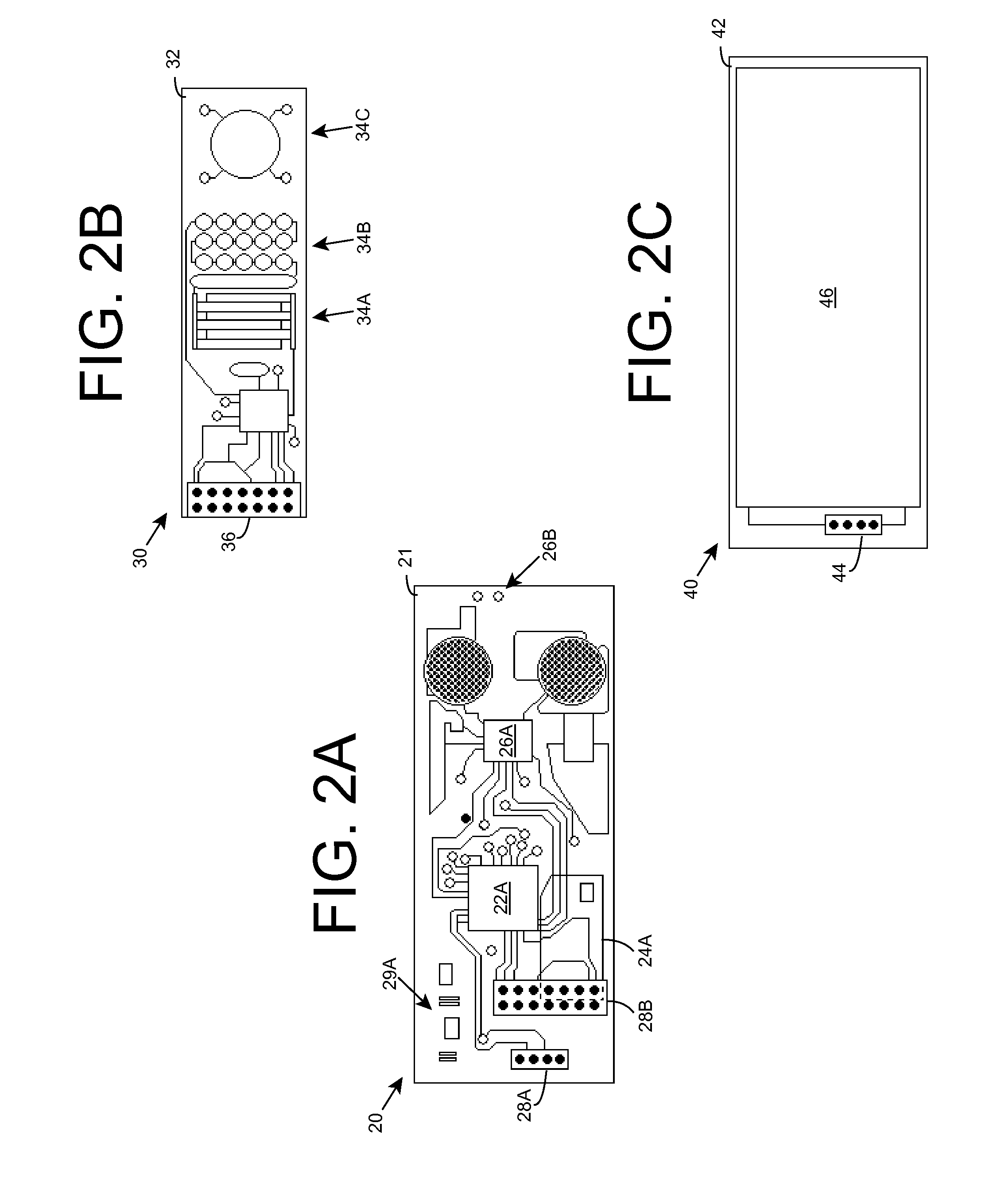
[0031]As indicated above, aspects of the invention provide an improved sensor node for use in a sensor system. In particular, the sensor system incorporates a set of sensor nodes for acquiring sensor data. Each sensor node is manufactured using separate components that can be matched according to a particular applicati...


PUM


Abstract

A sensor node for use in a sensor system includes a core component a sensor component and a power component. The core component includes processing and transmission / receiving components. Additionally, the core component includes interfaces for selectively connecting sensor and power components of any one of a plurality of types. In this manner, the core component enables the corresponding power and sensor components to be matched according to a particular application to generate the desired sensor node.

Description

REFERENCE TO PRIOR APPLICATIONS[0001]The current application claims the benefit of co-pending U.S. Provisional Application No. 61 / 054,907, titled “Sensor System”, which was filed on 21 May 2008, and which is hereby incorporated by reference. Aspects of the current application are related to U.S. Utility application Ser. No. 11 / 532,212, titled “MEMS-based Monitoring”, which was filed on 15 Sep. 2003 and issued as U.S. Pat. No. 7,412,899 on 19 Aug. 2008, and which is hereby incorporated by reference.GOVERNMENT LICENSE RIGHTS[0002]The U.S. Government has a paid-up license in this invention and the right in limited circumstances to require the patent owner to license others on reasonable terms as provided for by the terms of Contracts N68335-06-C-0216 and N68335-06-C-0217 awarded by the United States Navy / NAVAIR.TECHNICAL FIELD[0003]The disclosure relates generally to monitoring systems, and more particularly, to an improved sensor node.BACKGROUND ART[0004]Current wireless sensor approa...

Claims


Application Information

Patent Timeline
IPC IPC(8): G06F1/26G06F1/12
CPCG01D9/005H04J3/0655H04Q9/00
Inventor MIAN, ZAHID F.SPOOR, RYK E.MCKENNEY, BRUCE P.HAYES, PETER R.LEET, RANDY A.
Owner INT ELECTRONICS MACHINES
Features
  • Generate Ideas
  • Intellectual Property
  • Life Sciences
  • Materials
  • Tech Scout
  • Unparalleled Data Quality
  • Higher Quality Content
  • 60% Fewer Hallucinations
Learn More