Modular MIDI controller

a module and controller technology, applied in the field of electronic devices, can solve the problems of difficult or impossible to find a product that is suitable for several different types of applications, prohibitively expensive, and multiple controllers can occupy a large amount of space, and achieve the effect of easy reconfiguration of the typ

Inactive Publication Date: 2009-12-10
GYNES DESHKO
View PDF1 Cites 74 Cited by
  • Summary
  • Abstract
  • Description
  • Claims
  • Application Information

AI Technical Summary

Benefits of technology

[0009]The need in the art is addressed by the modular MIDI controller of the present invention. The novel controller includes two or more modules, each module including a plurality of controls, and a mechanism for connecting the modules together to form one unit. In an illustrative embodiment, each control is adapted to convert a mechanical action by a user into an electrical signal, and each module includes a processor adapted to convert the electrical signals from the controls into control messages. A system control unit receives the control messages from each module and generates a corresponding MIDI output. In a preferred embodiment, the controller includes a plurality of chassis connected together to form a controller having a desired size and shape. Each chassis is adapted to hold one or more modules and may include a slot for holding one or more removable modules. The multiple connecting chassis allow the user to adjust the size and shape of the controller, while the removable modules allow the user to easily reconfigure the type and number of controls in the controller.

Problems solved by technology

A user can typically find a controller that is well suited for one particular application; however, it may be difficult or impossible to find a product that is suitable for several different types of applications.
This can become prohibitively expensive and the multiple controllers can occupy a large amount of space, which is typically very limited in a studio environment.
Currently, there is no single MIDI controller that can be reconfigured to meet the requirements of different applications.

Method used


Image

  • Modular MIDI controller
  • Modular MIDI controller
  • Modular MIDI controller

Examples


Embodiment Construction

[0018]Illustrative embodiments and exemplary applications will now be described with reference to the accompanying drawings to disclose the advantageous teachings of the present invention.

[0019]While the present invention is described herein with reference to illustrative embodiments for particular applications, it should be understood that the invention is not limited thereto. Those having ordinary skill in the art and access to the teachings provided herein will recognize additional modifications, applications, and embodiments within the scope thereof and additional fields in which the present invention would be of significant utility.

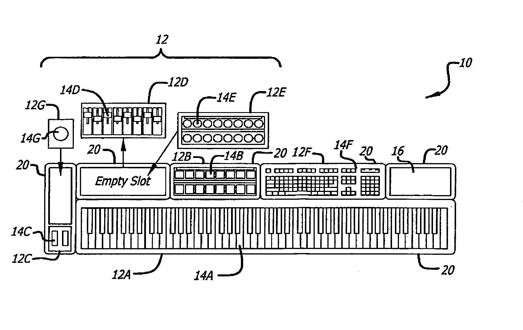
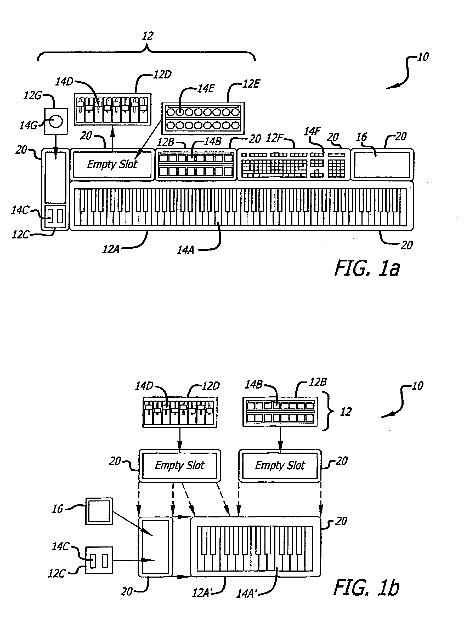
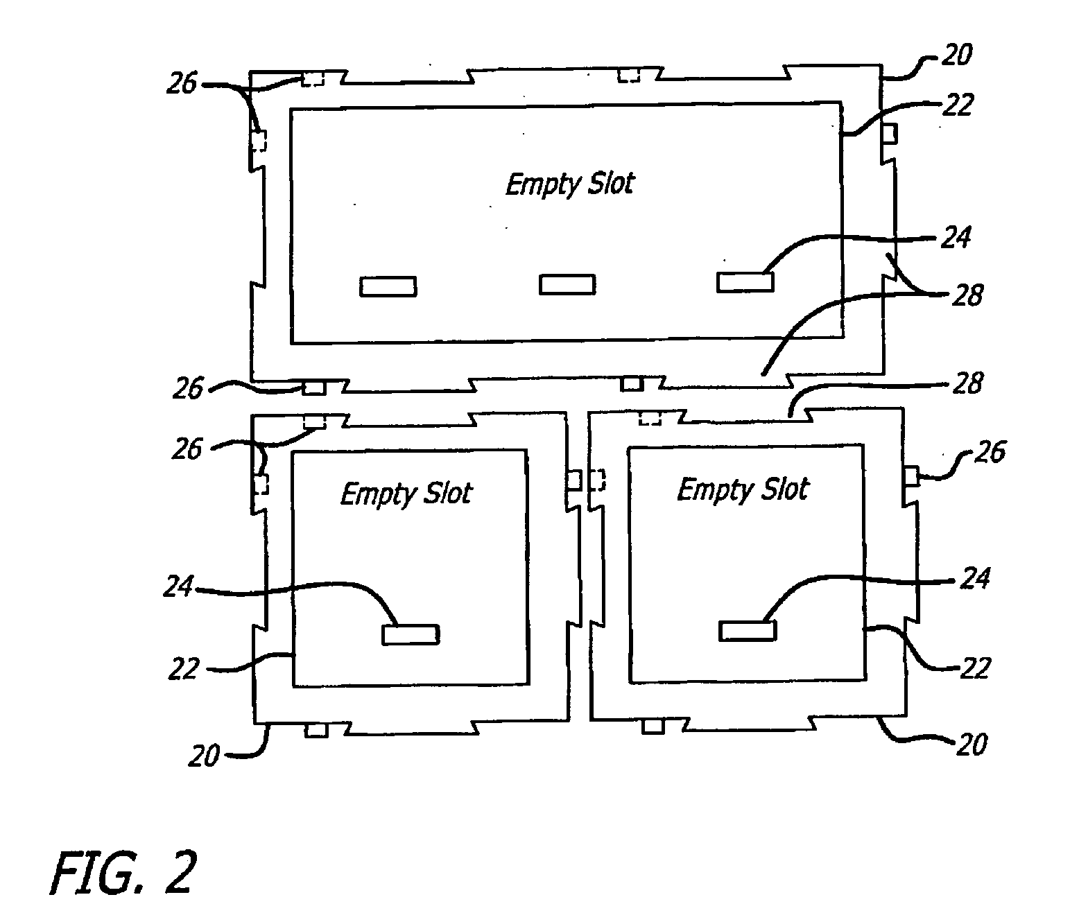
[0020]The present invention provides a novel MDI controller having a unique modular design that allows a user to reconfigure the controller as desired, changing the types and numbers of controls in the controller as well as its overall size and shape.

[0021]FIG. 1a is a simplified diagram of a modular MIDI controller 10 designed in accordance with an ...


PUM


Abstract

A modular MIDI controller. The novel controller includes two or more modules, each module including a plurality of controls, and a mechanism for connecting the modules together to form one unit. In an illustrative embodiment, each control is adapted to convert a mechanical action by a user into an electrical signal, and each module includes a processor adapted to convert the electrical signals from the controls into control messages. A system control unit receives the control messages from each module and generates a corresponding MIDI output. In a preferred embodiment, the controller includes a plurality of chassis connected together to form a controller having a desired size and shape. Each chassis is adapted to hold one or more modules and may include a slot for holding one or more removable modules.

Description

BACKGROUND OF THE INVENTION[0001]1. Field of the Invention[0002]The present invention relates to electronics. More specifically, the present invention relates to MIDI (Musical Instrument Digital Interface) controllers.[0003]2. Description of the Related Art[0004]MIDI (Musical Instrument Digital Interface) is a protocol that enables electronic musical instruments to interact with each other or with a computer or other electronic equipment. The MIDI data format is comprised of a series of event messages, such as “note on” and “note off” messages for indicating when a musical note should be played and at what pitch and intensity, and “control change” messages for controlling effects such as modulation, pan, sustain, reverb, etc. The MIDI signal is therefore not an audio signal, but digital message data that can be converted to an audio signal by a synthesizer or other sound generator. MIDI messages can also be used to control other types of MIDI compatible electronics such as lighting ...

Claims


Application Information

Patent Timeline
Patent Type & Authority Applications(United States)
IPC IPC(8): G10H7/00
CPCG10H1/0066G10H2220/096G10H1/34G10H2220/256
Inventor GYNES, DESHKO
Owner GYNES DESHKO
Why Eureka
Try Eureka