Gas removal device

a technology of gas removal device and gas filter, which is applied in the direction of liquid degasification, membranes, separation processes, etc., can solve the problems of inability to easily change, and achieve the effects of preventing buckling, reducing stress, and reducing buckling

Inactive Publication Date: 2009-12-10
NITTO DENKO CORP
View PDF9 Cites 14 Cited by
  • Summary
  • Abstract
  • Description
  • Claims
  • Application Information

AI Technical Summary

Benefits of technology

[0005]In view of the foregoing, the present invention is intended to provide a gas removal device in which the buckling of the gas-permeable tubes is prevented, and that exerts high degassing performance.
[0007]In the gas removal device of the present invention, the plurality of gas-permeable tubes is tied by the tying member to make the tube bundle. The tube bundle is bent in such a manner that a portion tied by the tying member is included in the bent portion. When the tube bundle is bent, bending stress is generated in the gas-permeable tubes. The gas-permeable tubes tend to change their form into one that can alleviate the stress, but such a change cannot be made easily because a tying force of the tying member is acting on them. As a result, the occurrence of buckling is prevented. The liquid to be degassed circulates smoothly in the gas-permeable tubes that are not buckled, and thereby a gas removal device exerting high degassing performance can be realized.
[0008]In another aspect, the present invention provides a gas removal device including a decompression chamber with an inlet and an outlet through which a liquid to be degassed flows in and out, and a degassing element that is accommodated in the decompression chamber while having one end connected to the inlet and another end connected to the outlet, and that allows the liquid to be degassed entering into the inlet to pass through the degassing element. The degassing element includes a tube bundle composed of a plurality of gas-permeable tubes, and a tying member winding spirally around the tube bundle to tie the plurality of gas-permeable tubes. At least a part of the tube bundle wound by the tying member is bent. The same effect can be obtained by such a configuration.

Problems solved by technology

The gas-permeable tubes tend to change their form into one that can alleviate the stress, but such a change cannot be made easily because a tying force of the tying member is acting on them.

Method used


Image

  • Gas removal device
  • Gas removal device
  • Gas removal device

Examples


embodiment 1

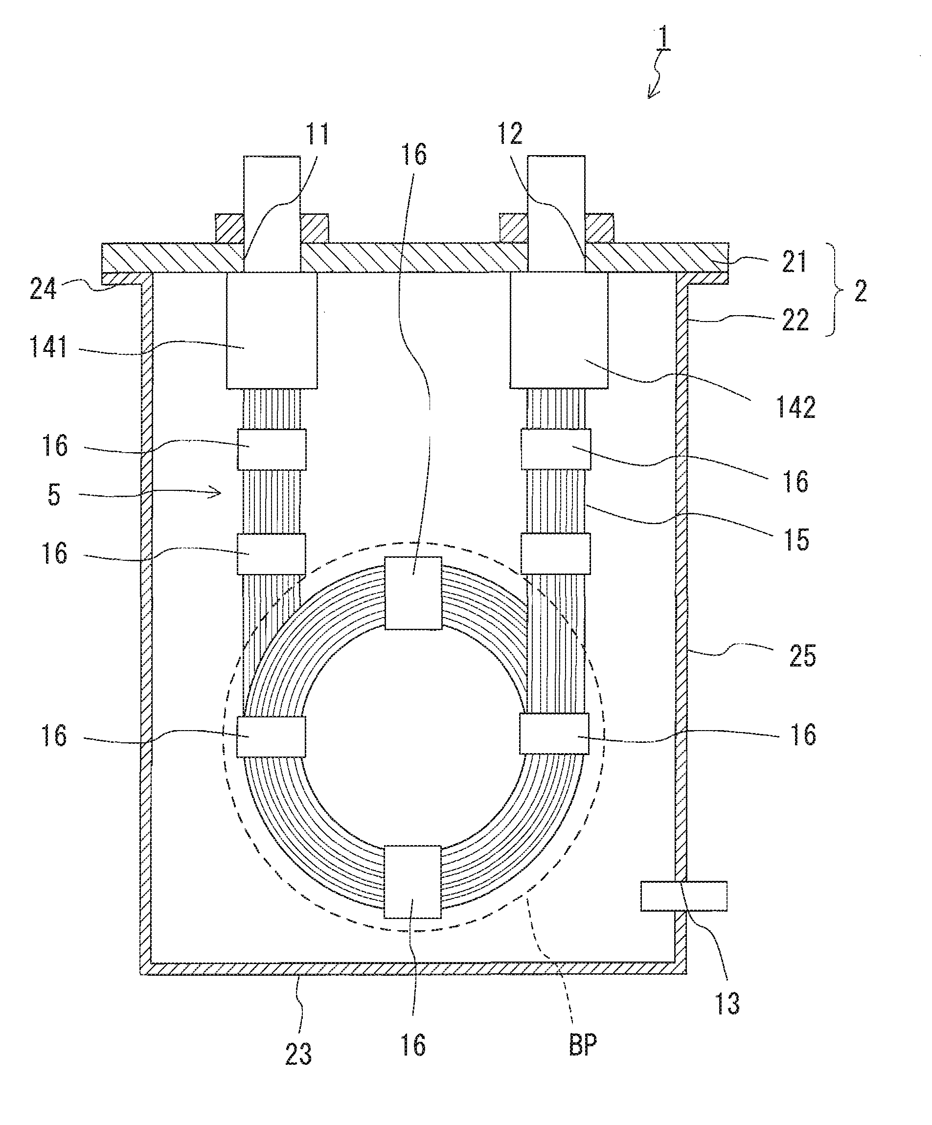
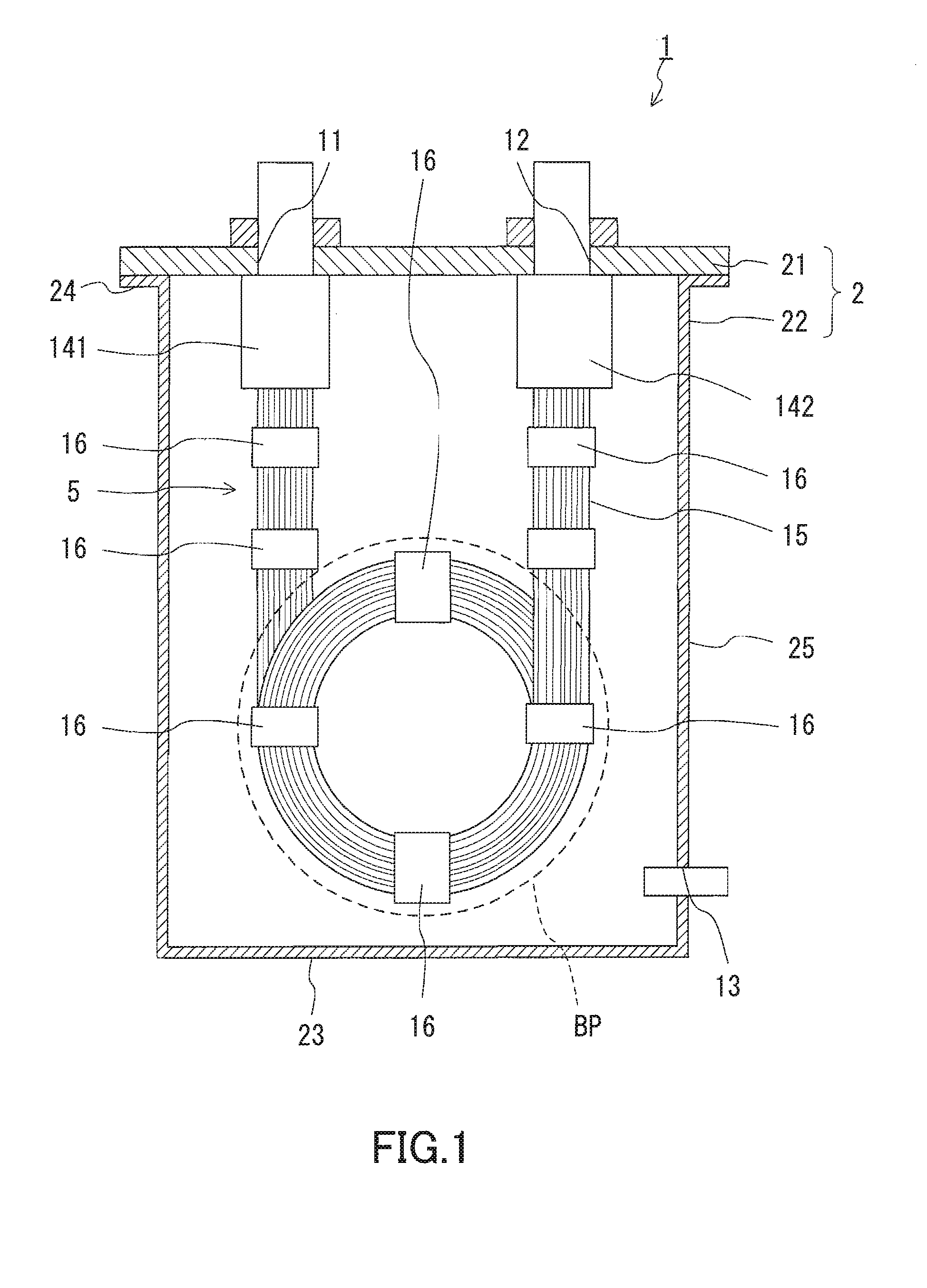
[0019]FIG. 1 shows a gas removal device of Embodiment 1 of the present invention. The gas removal device 1 includes a decompression chamber 2. The decompression chamber 2 includes an inlet 11 and an outlet 12 through which a liquid to be degassed circulates, and a vacuum suction port 13 to be connected to a decompression device. The decompression chamber 2 has a cover 21, and a chamber main body 22 with a tubular shape. The chamber main body 22 has a bottom portion 23 and an opening portion 24. The inlet 11 and the outlet 12 are provided at the cover 21. The vacuum suction port 13 is provided at a side part 25 of the chamber main body 22. The cover 21 is fixed to the opening portion 24 of the chamber main body 22 in such a manner that airtightness in the decompression chamber 2 is maintained. A degassing element 5 is disposed in the decompression chamber 2. The degassing element 5 has an end connected to the inlet 11 and another end connected to the outlet 12.

[0020]As shown in FIG. ...

embodiment 2

[0036]FIG. 6 shows a gas removal device of Embodiment 2 of the present invention. A difference between the gas removal device of Embodiment 1 described previously and the gas removal device of Embodiment 2 is the way of tying the gas-permeable tubes constituting the degassing element. Other configurations are common between the embodiments, as understood from the fact that they use the same reference numerals.

[0037]As shown in FIG. 6, the gas removal device 10 of the present embodiment includes the decompression chamber 2, and a degassing element 50 disposed in the decompression chamber 2. The configuration of the decompression chamber 2 is as described in Embodiment 1. As shown in FIG. 7, the degassing element 50 is composed of the tube bundle 15 including the plurality of gas-permeable tubes 151, a tying member 17 tying the gas-permeable tubes 151, and the adapters 141 and 142.

[0038]The degassing element 50 is accommodated in the decompression chamber 2 while the tube bundle 15 is...


PUM

PropertyMeasurementUnit
flexibleaaaaaaaaaa
gas permeabilityaaaaaaaaaa
shapeaaaaaaaaaa

Abstract

A gas removal device 1 includes a decompression chamber 2 with an inlet 11 and an outlet 12 through which a liquid to be degassed flows therein and thereout, and a degassing element 5 that is accommodated in the decompression chamber 2 while having one end connected to the inlet 11 and another end connected to the outlet 12, and that allows the liquid to be degassed entering into the inlet 11 to pass through the degassing element 5. The degassing element 5 includes a tube bundle 15 composed of a plurality of flexible gas-permeable tubes 151, and a tying member 16 tying the plurality of gas-permeable tubes 151 to form the tube bundle 15. The tube bundle 15 is bent in a shape of coil with multiple turns in such a manner that a portion tied by the tying member 16 is included in a bent portion BP.

Description

TECHNICAL FIELD[0001]The present invention relates to a gas removal device for removing gases from a liquid.BACKGROUND ART[0002]A dissolved gas in a liquid may cause corrosion of tubes through which a liquid flows, decrease in heat exchanger effectiveness and pressure due to bubble generation, and uneven application of a liquid due to generated bubbles. Hence, depending on the method and purpose of using a liquid, degassing is required.[0003]For example, a gas removal device disclosed in JP 11-333206 A can be used for degassing a liquid (see FIG. 9). In a gas removal device 101 shown in FIG. 9, a gas-permeable tube 103 is accommodated in a decompression chamber 102 with an inlet 111 and an outlet 112 through which the liquid to be degassed flows in and out. One end of the gas-permeable tube 103 is connected to the inlet 111 and another end is connected to the outlet 112. A vacuum suction pipe 104 reaching a bottom portion in the decompression chamber 102 is attached to the decompres...

Claims


Application Information

Patent Timeline
Patent Type & Authority Applications(United States)
IPC IPC(8): B01D19/00
CPCB01D19/0031B01D53/22B01D63/024B01D2313/21B01D2313/06B01D2313/12B01D2313/20B01D63/025B01D19/00B01D61/00B01D71/36
Inventor OOYA, HAJIME
Owner NITTO DENKO CORP
Why Eureka
Try Eureka