Mower with cushioned suspension for operator support platform having stowed and deployed positions

a technology of operator support platform and cushioned suspension, which is applied in the field of mowers, can solve the problems of uneven ride of the same bumps and shocks that the mower is subject to, and the ride experienced by the operator who stands on the support platform can be quite rough

Inactive Publication Date: 2009-12-10
TORO CO THE
View PDF21 Cites 17 Cited by
  • Summary
  • Abstract
  • Description
  • Claims
  • Application Information

AI Technical Summary

Problems solved by technology

Thus, the support platform is subjected to the same bumps and shocks experienced by the traction frame as the mower is driven over the ground.
Since the traction frame of such a mower is not usually cushioned to provide a soft ride, the bumps or shocks encountered by the mower are transmitted through to the support platform largely unabated.
Consequently, the ride experienced by the operator who stands on the support platform can be quite rough particularly when the mower is operating over uneven terrain.
This can be uncomfortable and annoying to the operator.
Moreover, it can be difficult for the operator to keep his or her balance on the support platform which is a distraction for the operator.
Thus, the use of a rigidly supported platform on the traction frame can potentially interfere with the safe operation of the mower and certainly makes the task of operating the mower more tiring for the operator.
However, in known mowers of this type, the amount of travel allowed for the support platform is very small, e.g. about ½″.
Thus, there will be times when the support platform bottoms out and the operator is still subjected to shocks and bumps encountered by the mower.

Method used


Image

  • Mower with cushioned suspension for operator support platform having stowed and deployed positions
  • Mower with cushioned suspension for operator support platform having stowed and deployed positions
  • Mower with cushioned suspension for operator support platform having stowed and deployed positions

Examples


Embodiment Construction

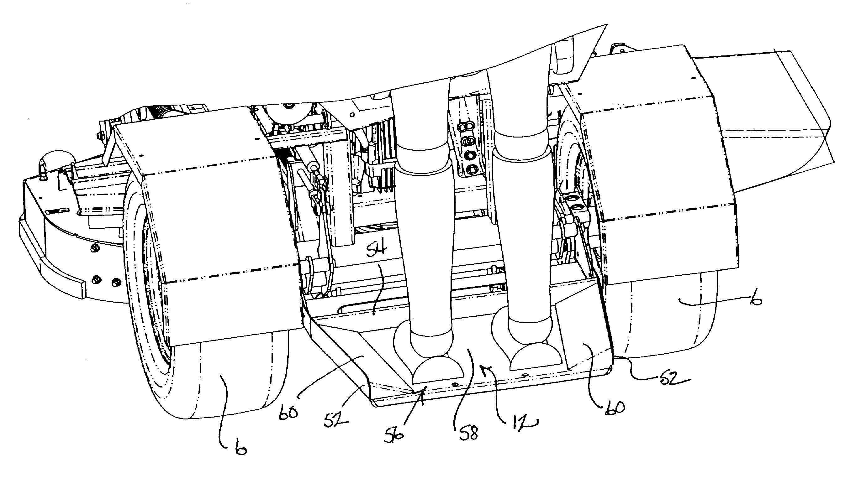
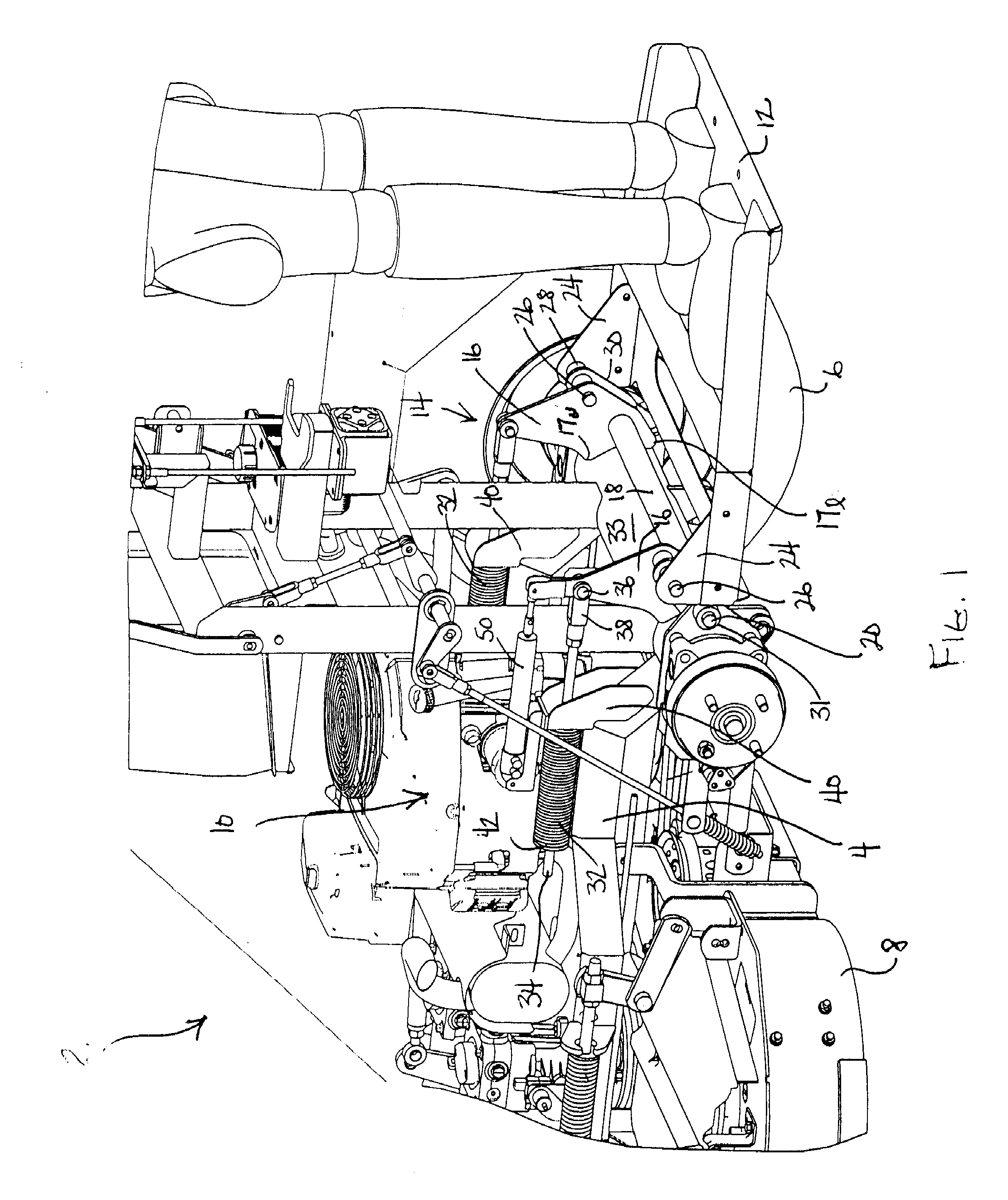
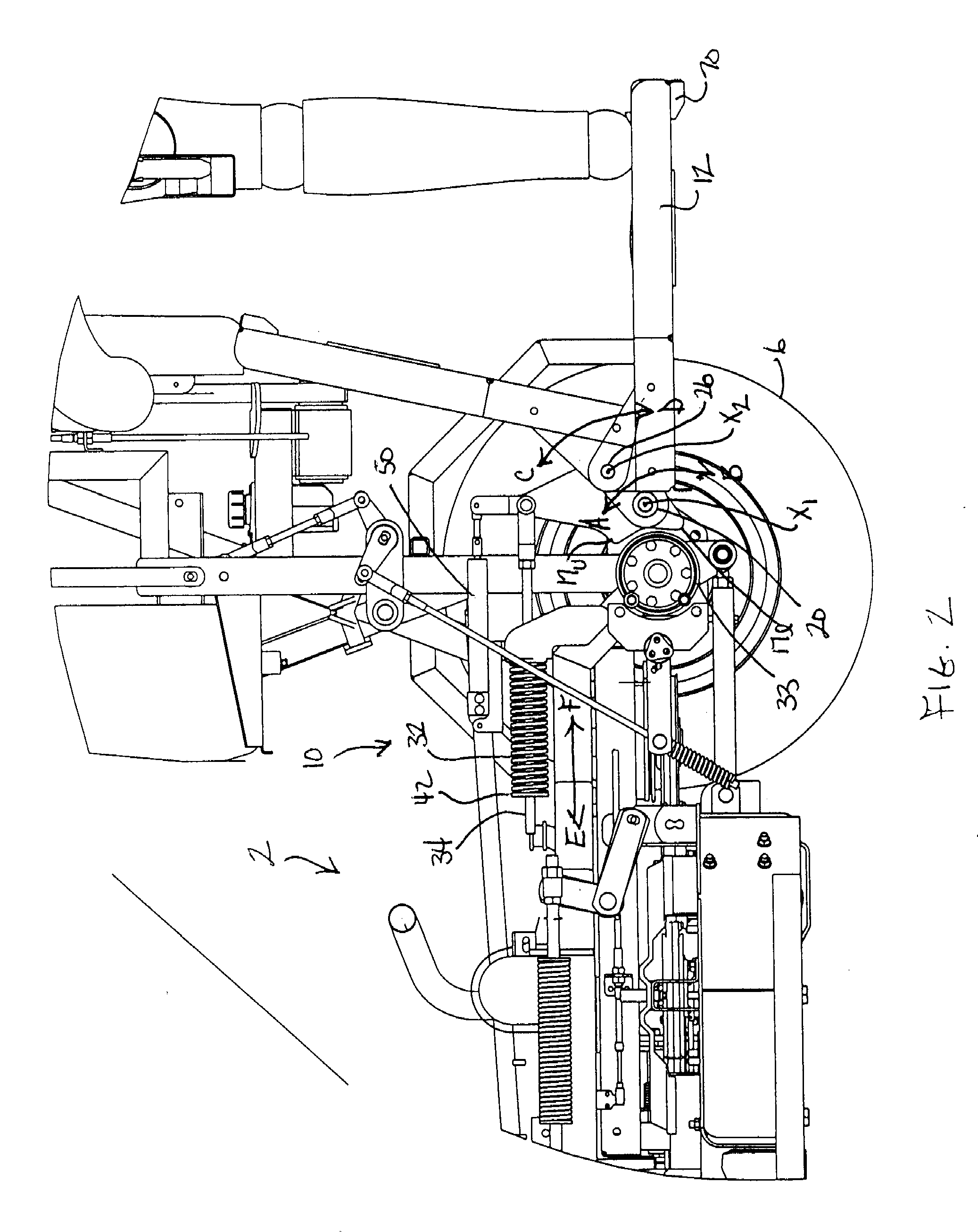
[0019]One embodiment of a mower according to this invention is illustrated generally as 2. Only the rear of mower 2 is illustrated since this is the portion of mower 2 that carries the improvement of this invention.

[0020]Mower 2 comprises a traction frame 4 that is propelled over the ground by a pair of rear drive wheels 6. See FIG. 6. Only drive wheel 6 on the far side of mower 2 is shown in FIGS. 1-4 with drive wheel 6 on the near side of mower 2 having been removed for the purpose of clarity. Drive wheels 6 are independently powered for forward and reverse operation by separate drive motors (not shown). Thus, mower 2 is capable of skid steer or zero radius turn operation.

[0021]The front of traction frame 4 carries a pair of unpowered caster wheels (not shown). A cutting deck 8 for mowing grass is suspended beneath a portion of traction frame 4 between the front caster wheels and rear drive wheels 6. Cutting deck 8 has one or more rotary cutting blades (not shown). Mowers 2 of thi...


PUM


Abstract

A stand-on riding mower has a support platform at the rear thereof for supporting an operator who stands during operation of the mower. The support platform is pivotally connected to the traction frame of the mower by a suspension that includes pivotal support plates at each side of the platform. At least one spring is arranged to push against the pivotal support plates in a direction causing the platform to rise such that the weight of the operator atop the platform causes the platform to lower until increasing biasing force in the spring balances the operator's weight. The spring ensures that impact shocks and the like on the traction frame of the mower are cushioned before reaching the operator's platform. In addition, the operator's platform is pivotal relative to the support plates to allow the operator's platform to be disposed in both a vertical stowed position and a horizontal deployed position.

Description

CROSS REFERENCE TO RELATED APPLICATIONS[0001]This application is a continuation-in-part of application Ser. No. 12 / 002,798, filed Dec. 18, 2007, which claims the benefit of previously filed provisional Application Ser. No. 60 / 875,749, filed Dec. 19, 2006.TECHNICAL FIELD[0002]This invention relates to a mower that is operated by an operator who is supported in a standing position by a support platform.BACKGROUND OF THE INVENTION[0003]Various lawn mowers are known having a traction frame propelled by a pair of drive wheels. The drive wheels are independently driven by separate drive motors capable of both forward and reverse operation. A very sharp turn can be executed by operating one drive wheel in a forward direction while simultaneously operating the other drive wheel in a reverse direction. Such mowers are often referred to as skid steer mowers or zero radius turn mowers or the like.[0004]In some mowers of this type, the operator is carried at the rear of the mower atop a support...

Claims


Application Information

Patent Timeline
Patent Type & Authority Applications(United States)
IPC IPC(8): A01D75/00
CPCA01D34/82A01D34/64
Inventor KALLEVIG, JEFFREY B.GAMBLE, JESSE R.SCHERBRING, DAVID J.
Owner TORO CO THE
Why Eureka
Try Eureka