Rotary land leveler operating device based on short-tooth shape

A working device, rotary technology, applied in the direction of earthmoving machine/shovel, construction, etc., can solve the requirement of continuous and smooth motion of pinion meshing with rotary ring gear, difficult to guarantee, slow rotation speed of rotary ring gear, and worm gear. Worm fatigue damage and other problems, to achieve the effect of compact structure, improved reliability and extended service life

Inactive Publication Date: 2011-10-12
TONGJI UNIV
View PDF4 Cites 14 Cited by
  • Summary
  • Abstract
  • Description
  • Claims
  • Application Information

AI Technical Summary

Problems solved by technology

However, the tooth profile of the rotary ring gear and the pinion is still reduced by profiling (or shaping) to reduce the number of teeth of the pinion to achieve a larger transmission ratio. The quality of the processed tooth profile is usually not easy to guarantee (and the processing cost is not low), because it is a non-standard tooth shape, it is difficult to guarantee the continuous and smooth movement of the pinion and the slewing ring gear (in fact, because the slewing ring speed is relatively slow, even if there is a certain difference Continuous, not easy to show)
[0006] With the slewing bearing type slewing ring gear, the gear can adopt the involute standard tooth shape, but it is difficult to reduce the number of teeth of the pinion to a small value, and the increased torque will move forward to the worm gear, which is easy to appear. fatigue damage

Method used


Image

  • Rotary land leveler operating device based on short-tooth shape
  • Rotary land leveler operating device based on short-tooth shape
  • Rotary land leveler operating device based on short-tooth shape

Examples


Embodiment Construction

[0040] The present invention is further illustrated below by means of embodiments in conjunction with the accompanying drawings.

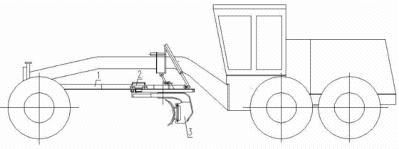
[0041] figure 1 It is the outline drawing of the rotary grader. The working device of the rotary grader is composed of a traction frame 1, a rotary mechanism 2 and a blade body assembly 3.

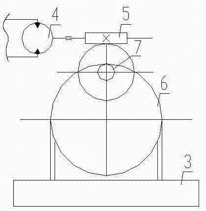
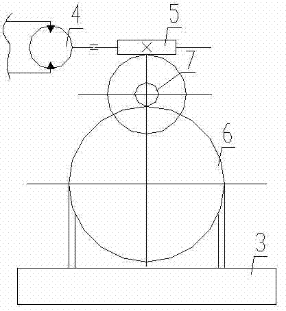
[0042] figure 2 , image 3 They are the internal meshing transmission schematic diagram and the external meshing transmission schematic diagram of the slewing mechanism of the motor grader respectively. The slewing mechanism of the motor grader is composed of a hydraulic motor 4 , a worm gear reducer 5 , and a slewing ring gear 6 . Wherein, the hydraulic motor 4 and the worm gear reducer 5 form an integral body, and are fixed on the traction frame 1 with bolts. The output torque of the hydraulic motor 4 is decelerated by the worm gear reducer 5 to realize deceleration and torque increase. The coaxial pinion 7 is installed on the worm gear, and the pinion...


PUM


Abstract

The invention relates to a rotary land leveler operating device based on a short-tooth shape. The device consists of a traction frame, a rotary mechanism and a shovel blade body assembly; the rotary mechanism consists of a hydraulic motor, a worm wheel / gear speed reduction box and a rotary gear ring; the hydraulic motor and the worm wheel / gear speed reduction box are integrated into a whole; a co-axial pinion is arranged on a worm wheel of the worm wheel / gear speed reduction box; the co-axial pinion is engaged with the rotary gear ring; the rear end of the traction frame lifts the rotary gear ring to the lower part of the traction frame through a guide plate; the rotary gear ring can do rotary motion on the lower part of the traction frame; the shovel blade body assembly consists of a support, an angle retainer and a shovel blade; the support is fixed on the rotary gear ring; the angle retainer is fixed on an angle retainer installation shaft positioned on the support; the shovel blade is connected with a horizontal hydraulic oil cylinder and arranged on a sliding rail; the angle retainer is connected with one end of the sliding rail; and the rotary gear ring can be replaced by a rotary support structure with an internal ring and an external ring, and a connection mode is also required to be correspondingly adjusted. By the device, a land leveler rotary mechanism is simple in structure and has long service life, the reliability of the rotary land leveler working device is greatly improved, and the reliability of the whole land leveler is greatly and correspondingly improved.

Description

technical field [0001] The invention belongs to the technical field of mechanical engineering, and in particular relates to a rotary motor grader working device based on a short tooth profile. Background technique [0002] A grader is an earth-moving machine that uses a shovel (scraper) to level the ground. The assembly of the blade (body) and other devices to ensure that the blade (body) completes a variety of tasks is usually called a grader working device. The blade (body) is a working device with six degrees of freedom. The working device of the grader is composed of a swing frame, a traction frame, a rotary (mechanism) device and a blade (body) assembly. The swing frame is installed on the swing rail of the front frame and can rotate around the swing rail, and is connected with the traction frame by a hydraulic cylinder to realize the up and down movement and swing of the blade (body) (the front end of the traction frame is a ball joint). The front end of the traction...

Claims


Application Information

Patent Timeline
Patent Type & Authority Applications(China)
IPC IPC(8): E02F3/815E02F3/85
Inventor 吴仁智奚鹰林志育
Owner TONGJI UNIV
Why Eureka
Try Eureka