Organic electro-luminescent display device and manufacturing method thereof

Active Publication Date: 2009-12-10
LG DISPLAY CO LTD
View PDF6 Cites 50 Cited by
  • Summary
  • Abstract
  • Description
  • Claims
  • Application Information

AI Technical Summary

Benefits of technology

[0010]An object of the present embodiment is to provide an OLED device that includes a micro-lens portion on a sealant layer to protect organic light emission

Problems solved by technology

Due to this, the OLED device has a problem in that its optical reproductivity and light efficiency are d

Method used


Image

  • Organic electro-luminescent display device and manufacturing method thereof
  • Organic electro-luminescent display device and manufacturing method thereof
  • Organic electro-luminescent display device and manufacturing method thereof

Examples


Example

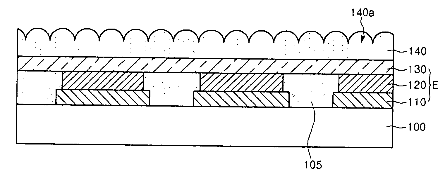
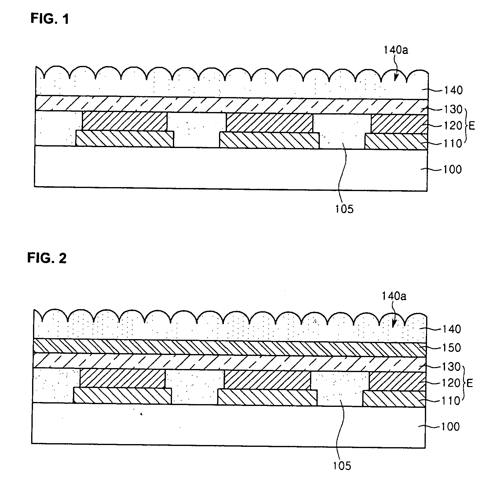
[0022]FIG. 1 is a cross sectional view showing an OLED device according to a first embodiment of the present disclosure. The OLED device according to the first embodiment of the present disclosure includes a plurality of pixels, but FIG. 1 largely shows only three pixels among the plural pixels displaying an image (or a picture), for the convenience of explanation. Referring to. FIG. 1, the LCD device of the first present embodiment includes organic light emission diode elements E, and a sealant layer 140 shielding the organic light emission diode elements E from external oxygen and / or moisture.

[0023]Particularly, the substrate 100 includes a plurality of pixels displaying an image (or a picture). Each of the pixels can include red, green, and blue sub-pixels. Also, driver elements applying drive signals to the organic light emission diode elements E are formed the substrate 100, but they are not shown in the drawing and are not described in this disclosure, for the convenience of e...

Example

[0037]FIG. 2 is a cross sectional view showing an OLED device according to a second embodiment of the present disclosure. The OLED device according to the second embodiment has the same structure as that of the first embodiment described above, with the exception of an auxiliary sealant layer. Accordingly, the description of the first embodiment to be repeated in the second embodiment of the present disclosure will be omitted. Also, the OLED device according to the second embodiment of the present disclosure will refer to the same reference numbers for the same elements as that according to the first embodiment.

[0038]Referring to FIG. 2, the OLED device of the second embodiment includes: organic light emission diode elements E arranged on a substrate 100; and a sealant layer 140 disposed on the substrate 100 to cover the organic light emission diode elements E. Each of the organic light emission diode elements E includes; a first electrode 110, an organic light emission layer 120 di...

Example

[0044]FIG. 3 is a cross sectional view showing an OLED device according to a third embodiment of the present disclosure. The OLED device according to the third embodiment has the same structure as that of the second embodiment described above, with the exception of a micro-lens portion. Accordingly, the description of the second embodiment to be repeated in the third embodiment of the present disclosure will be omitted. Also, the OLED device according to the third embodiment of the present disclosure will refer to the same reference numbers for the same elements as that according to the second embodiment.

[0045]Referring to FIG. 3, the OLED device of the second embodiment includes: organic light emission diode elements E arranged on a substrate 100; and a sealant layer 140 disposed on the substrate 100 to cover the organic light emission diode elements E.

[0046]The sealant layer 140 includes a micro-lens portion 140a, thereby improving the light efficiency and protecting the organic l...


PUM


Abstract

An OLED device and a manufacturing method thereof, which can secure the life span and reliability and can improve light efficiency, is disclosed.
To this end, the device and method disposes organic light emission diode elements on a substrate. On the substrate with the organic light emission diode elements, a sealant layer having a micro-lens portion is disposed, thereby shielding the organic light emission diode elements from external moisture and/or oxygen.

Description

CROSS-REFERENCE TO RELATED APPLICATION[0001]This application claims priority under 35 U.S.C. 119 to Korean Patent Application No. 10-2008-0052757, filed on Jun. 4, 2008, which is hereby incorporated by reference in its entirety.BACKGROUND[0002]1. Field of the Disclosure[0003]This disclosure relates to an organic electro-luminescent display device adapted to improve the life span, reliability, and light efficiency of its light emission diodes, and to a manufacturing method thereof.[0004]2. Description of the Related Art[0005]Display devices have been developed along with the development of information communication and have became a modern-day necessity. Of the display devices, organic electro-luminescence display (OLED) devices can be light and slim since they do not need backlight units required for liquid crystal display devices. Also, the OLED devices can be manufactured through a simple process and can have price competitive prices. Moreover, the OLED devices have a low voltage ...

Claims


Application Information

Patent Timeline
IPC IPC(8): H01J1/62H01J9/32
CPCH01L27/32H01L51/5275H01L51/5237H10K59/00H10K50/844H10K50/858H01L33/52H05B33/04H10K50/841H10K50/84
Inventor KIM, OCK HEELEE, KANG JU
Owner LG DISPLAY CO LTD
Why Eureka
Try Eureka