Apparatus for Sub-Wavelength Near-Field Focusing of Electromagnetic Waves

a near-field focusing and electromagnetic wave technology, applied in the field of sub-wavelength near-field focusing techniques, can solve the problems of standard interference techniques and geometrical optics methods not applying

Active Publication Date: 2009-12-10
RGT UNIV OF MICHIGAN
View PDF7 Cites 52 Cited by
  • Summary
  • Abstract
  • Description
  • Claims
  • Application Information

AI Technical Summary

Problems solved by technology

Because of this, standard interference techniques and geometrical optics methods do not apply.

Method used


Image

  • Apparatus for Sub-Wavelength Near-Field Focusing of Electromagnetic Waves
  • Apparatus for Sub-Wavelength Near-Field Focusing of Electromagnetic Waves
  • Apparatus for Sub-Wavelength Near-Field Focusing of Electromagnetic Waves

Examples


Embodiment Construction

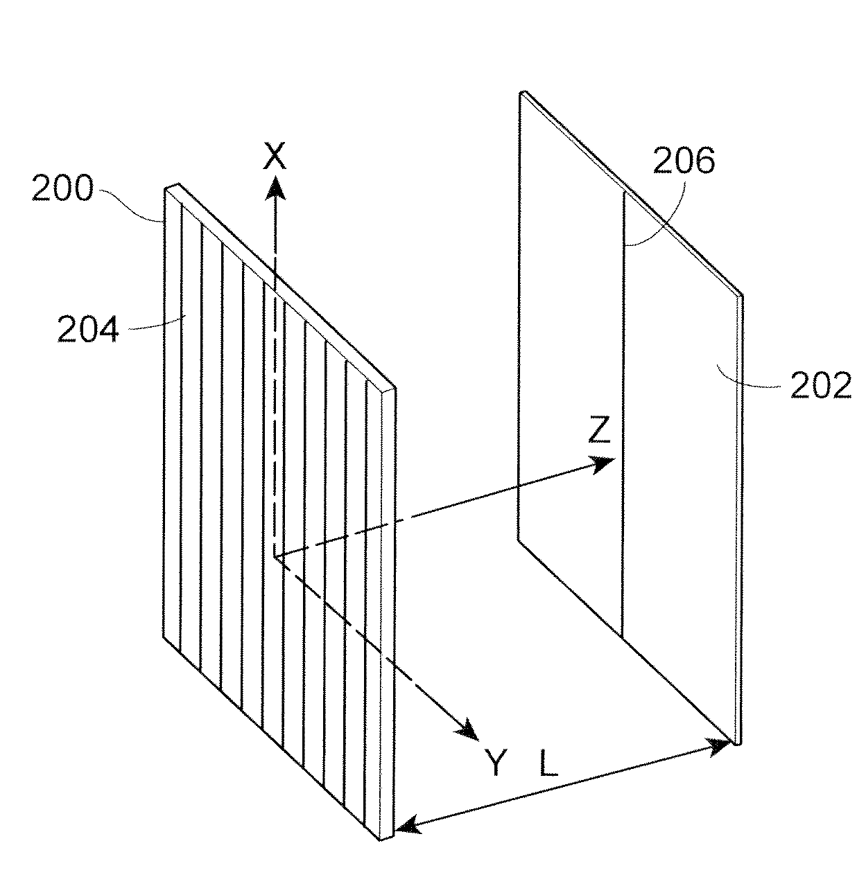
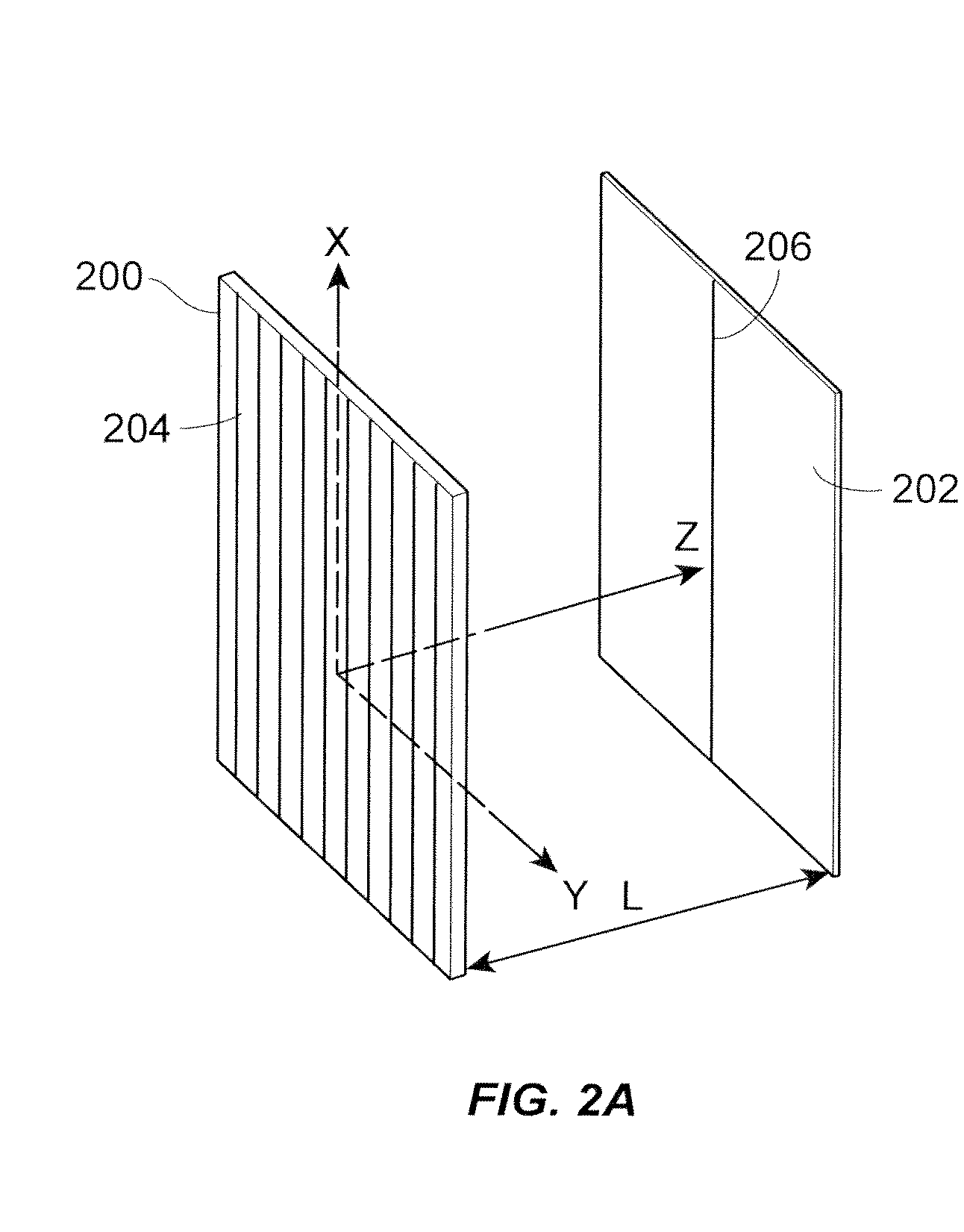
[0028]To provide background on the techniques herein, take F as one of the Cartesian components of the electric (E) or the magnetic field (H) of an electromagnetic wave. Assume that all field sources are monochromatic, with time-dependence given by e−iωt (where ω is the angular frequency). Further assume that each field is orientated to originate from one side of a particular plane, defined as z=0. Then, for z≧0, F satisfies the Helmholtz wave equation ∇2F+k2F=0 and can thus be expressed in the form:

F(x,y,zα)=14π2∫∫∫∫-∞+∞F(x′,y′,zβ)[qx(x-x′)+qy(y-y′)+κ(zα-zβ)]x′y′qxqy(1)

which provides an exact relationship between the solution to the wave equation in two arbitrary planes parallel to each other and above z=0, i.e., z=zα>0 and z=zβ>0. With k=2π / λ, κ in the F field expression Eq. (1) will have one of the following two values depending on the relative values shown:

κ={(qx2+qy2-k2)1 / 2qx2+qy2≥k2(k2-qx2-qy2)1 / 2qx2+qy2<k2(2)

With the F field source originating in the half-space z<0, the ch...


PUM


Abstract

Planar sub-wavelength structures provide superlensing, i.e., electromagnetic focusing beyond the diffraction limit. The planar structures use diffraction to force the input field to converge to a spot on the focal plane. The sub-wavelength patterned structures manipulate the output wave in such a manner as to form a sub-wavelength focus in the near field. In some examples, the sub-wavelength structures may be linear grating-like structures that can focus electromagnetic radiation to lines of arbitrarily small sub-wavelength dimension, or two dimensional grating-like structures and Bessel (azimuthally symmetric) structures that can focus to spots of arbitrarily small sub-wavelength dimensions. The particular pattern for the sub-wavelength structures may be derived from the desired focus. Some examples describe sub-wavelength structures that have been implemented to focus microwave radiation to sub-wavelength dimensions in the near field.

Description

CROSS REFERENCE TO RELATED APPLICATIONS[0001]The present application claims the benefit of U.S. Provisional Application No. 60 / 938,858, entitled “Apparatus for Sub-Wavelength Near-Field Focusing of Electromagnetic Waves”, filed on May 18, 2007, which is hereby incorporated by reference herein in its entirety.SPONSORED RESEARCH[0002]This invention was made with government support under FA9550-06-1-0279 and FA9550-07-1-0029, awarded by the Air Force Office of Scientific Research. The government has certain rights in the invention.FIELD OF THE INVENTION[0003]The present disclosure relates generally to techniques for focusing electromagnetic waves and, more particularly, to techniques for sub-wavelength near-field focusing.BACKGROUND OF RELATED ART[0004]The closely-related problems of electromagnetic imaging and focusing beyond Abbe's diffraction limit (set by ˜λ / n where λ is the vacuum wavelength and n is the refractive index) have received considerable attention in the past decade, mo...

Claims


Application Information

Patent Timeline
Patent Type & Authority Applications(United States)
IPC IPC(8): G21K1/00H01Q15/02G02B3/00
CPCB82Y20/00B82Y35/00Y10S977/707Y10S977/701G01Q60/22
Inventor GRBIC, ANTHONYMERLIN, ROBERTO D.
Owner RGT UNIV OF MICHIGAN
Why Eureka
Try Eureka