Combining geomechanical velocity modeling and tomographic update for velocity model building

a technology of tomographic update and velocity model, applied in the field of combining geomechanical velocity modeling and tomographic update for velocity model building, can solve the problem of computationally high cost of repeating inversion

Inactive Publication Date: 2009-12-10
WESTERNGECO LLC
View PDF12 Cites 42 Cited by
  • Summary
  • Abstract
  • Description
  • Claims
  • Application Information

AI Technical Summary

Benefits of technology

[0009]In another implementation, the velocity model may be an anisotropic velocity model. A difference between a combination produced by a first iteration and a combination produced by a second iteration of the steps described above may be determined. The steps may be repeated until the difference is less than a specified threshold. In yet another implementation, the velocity model may be an isotropic velocity model.
[0010]The claimed subject matter is not limited to implementations that solve any or all of the noted disadvantages. Further, the summary section is provided to introduce a selection of concepts in a simplified form that are further described below in the detailed description section. The summary section is not intended to identify key features or essential features of the claimed subject matter, nor is it intended to be used to limit the scope of the claimed subject matter.

Problems solved by technology

Repeating the inversion is computationally very expensive.

Method used


Image

  • Combining geomechanical velocity modeling and tomographic update for velocity model building
  • Combining geomechanical velocity modeling and tomographic update for velocity model building
  • Combining geomechanical velocity modeling and tomographic update for velocity model building

Examples


Embodiment Construction

[0016]The discussion below is directed to certain specific implementations. It is to be understood that the discussion below is only for the purpose of enabling a person with ordinary skill in the art to make and use any subject matter defined now or later by the patent “claims” found in any issued patent herein.

[0017]One or more implementations of various techniques for combining geomechanical velocity modeling and tomographic updates for velocity model building will now be described in more detail with reference to FIGS. 1-4 in the following paragraphs.

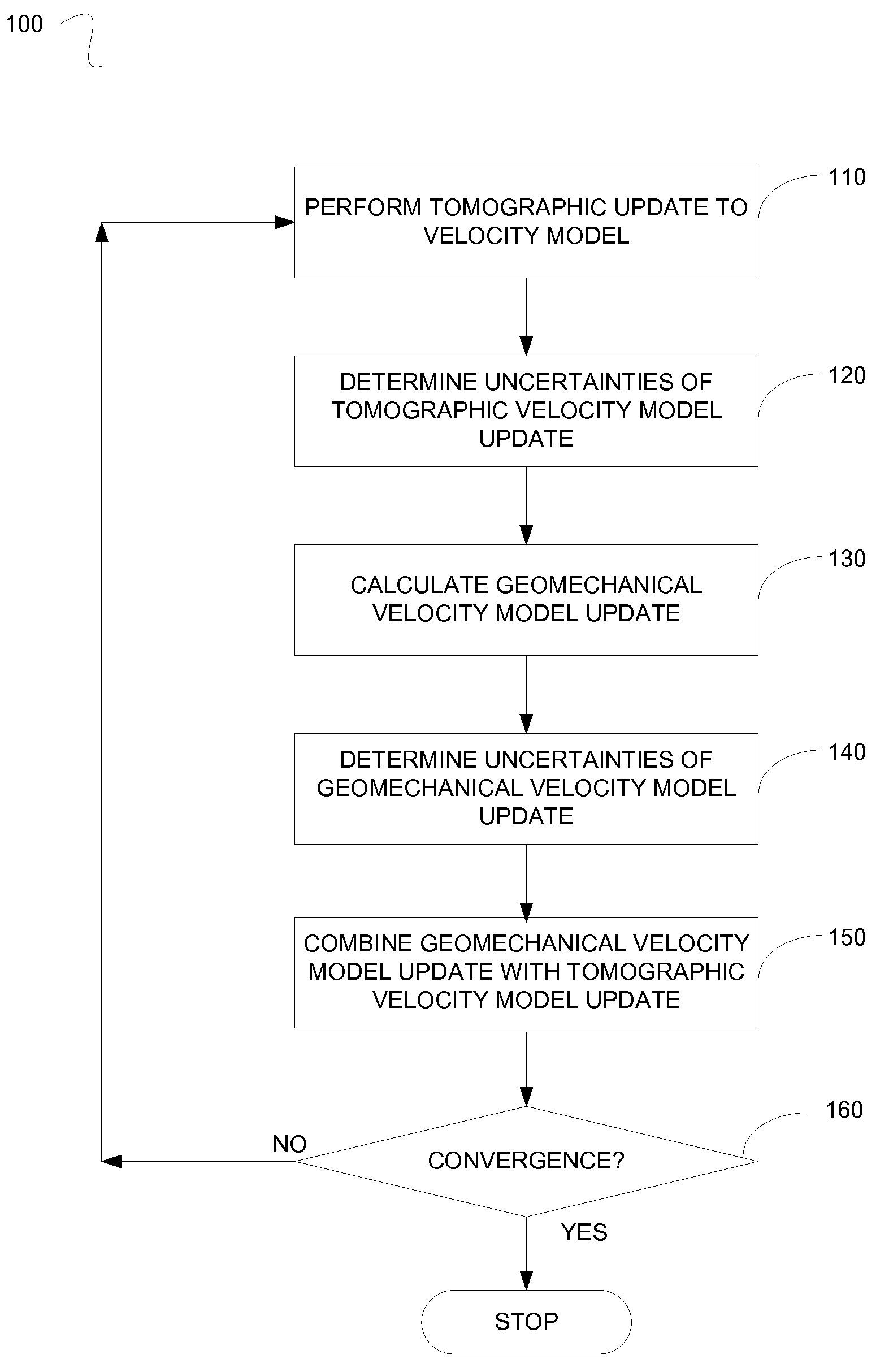
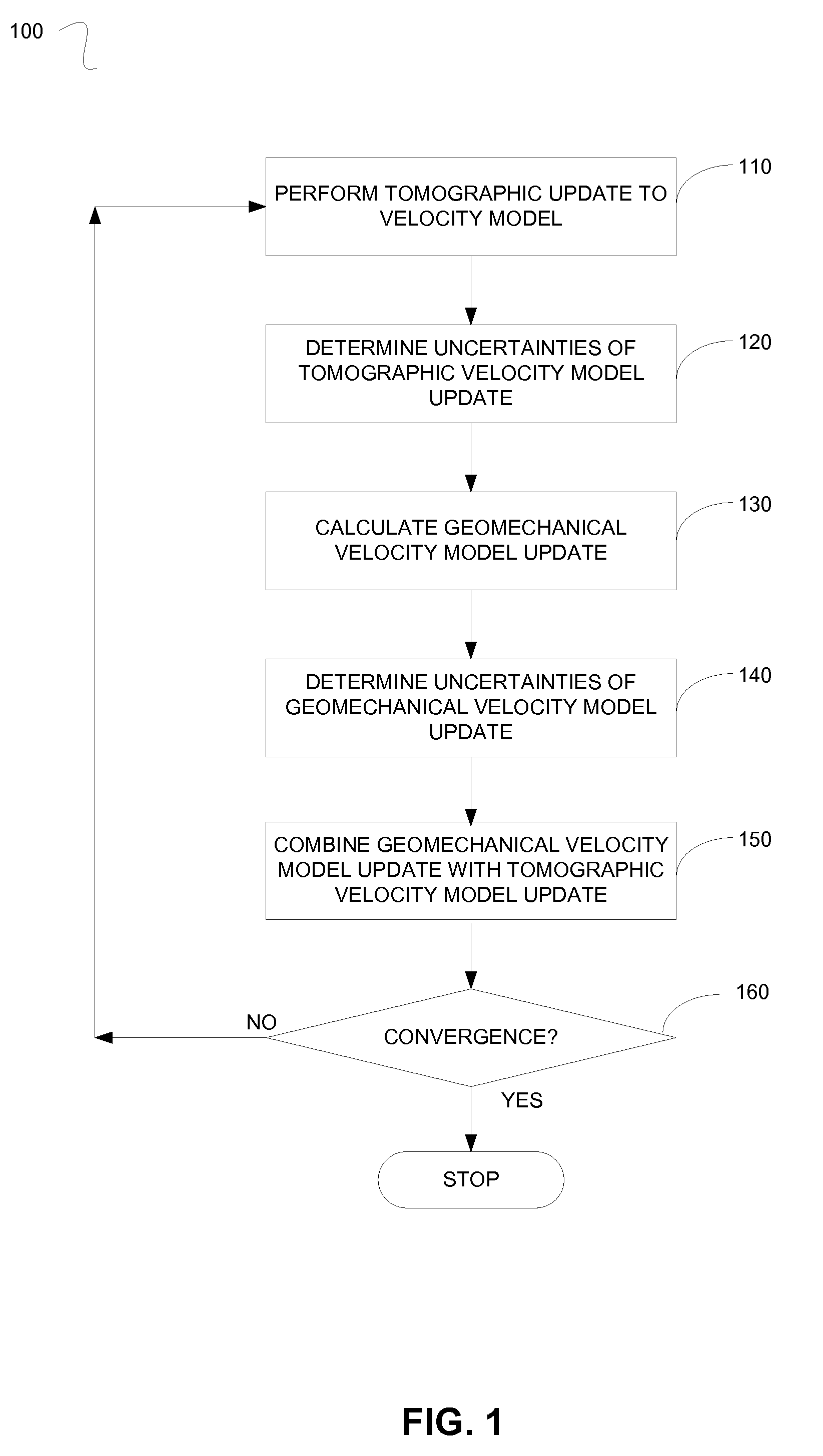
[0018]FIG. 1 is a flowchart illustrating a method 100 for combining geomechanical velocity modeling and a tomographic update for velocity model building in accordance with implementations described herein. It should be understood that while the flow chart indicates a particular order of execution of the operations, in some implementations, certain steps of method 100 may be executed in a different order.

[0019]At step 110, a tomograp...


PUM


Abstract

A method for updating a velocity model of a subsurface of the earth is described herein. A tomographic update to the velocity model of the subsurface may be performed to generate a tomographic velocity model update. A geomechanical velocity model update of the subsurface may be calculated. The geomechanical velocity model update may be combined with the tomographic velocity model update.

Description

CROSS-REFERENCE TO RELATED APPLICATIONS[0001]This application claims benefit of U.S. provisional patent application Ser. No. 61 / 059,220, filed Jun. 5, 2008, which is herein incorporated by reference.BACKGROUND[0002]Implementations of various technologies described herein generally relate to the field of geology and geophysics and more particularly, to combining geomechanical velocity modeling and tomographic update for velocity model building.1. Field of the Invention2. Description of the Related Art[0003]The following descriptions and examples do not constitute an admission as prior art by virtue of their inclusion within this section.[0004]Various techniques (e.g., electromagnetic or seismic techniques) exist to perform surveys of a subterranean structure for identifying subterranean bodies of interest. Examples of bodies of interest in the subterranean structure include hydrocarbon bearing reservoirs, gas injection zones, thin carbonate or salt layers, and fresh water aquifers. O...

Claims


Application Information

Patent Timeline
Patent Type & Authority Applications(United States)
IPC IPC(8): G01V1/28
CPCG01V1/303
Inventor SENGUPTA, MADHUMITABACHRACH, RANOSYPOV, KONSTANTIN S.
Owner WESTERNGECO LLC
Why Eureka
Try Eureka