Laser transmitter and method

Active Publication Date: 2009-12-10
TRIMBLE NAVIGATION LTD
View PDF12 Cites 5 Cited by
  • Summary
  • Abstract
  • Description
  • Claims
  • Application Information

AI Technical Summary

Benefits of technology

[0008]These needs are met by a laser transmitter according to the present invention for projecting a beam of laser light outward while raising and lowering the beam to define a conical surface of varying inclination relative to horizontal. The beam may be directed outward in all directions, or may be directed outward in less than all directions. The beam may define a cyclically varying conical surface, a non-cyclically varying conical surface, or a surface which changes inclination so as to track a laser receiver. The transmitter includes a laser source directing a beam generally vertically, and a beam diverting element. The beam diverting element is located in the path of the beam, intercepting the beam and redirecting it to emerge from the transmitter as a non-vertical beam that is raised and lowered to define conical reference surfaces. The beam may incrementally change in relative elevation angle according to a timed, predetermined schedule. The laser beam therefore defines a series of time-varying conical surfaces which illuminate a much wider range of heights in the surrounding environment. For exam

Problems solved by technology

While providing a very simple construction, a transmitter of this type is somewhat limited in operation and flexibility.
While fan beam systems provide for a broader range of coverage, such systems may have other draw backs, including a difficulty in extracting complete posi

Method used


Image

  • Laser transmitter and method
  • Laser transmitter and method
  • Laser transmitter and method

Examples


first embodiment

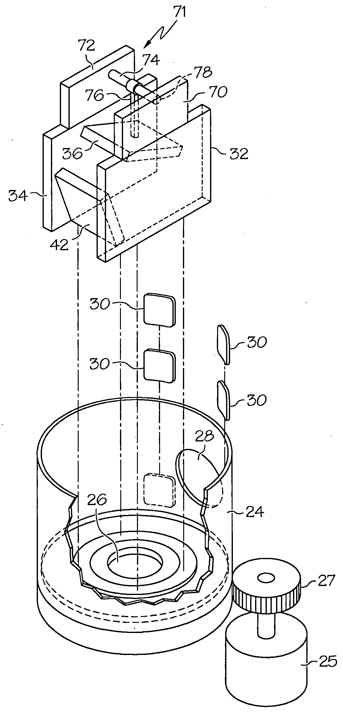
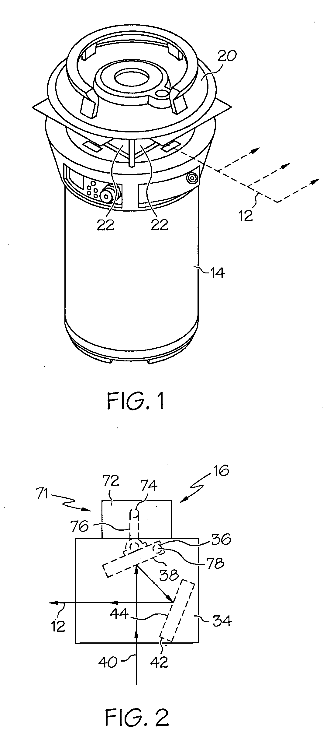
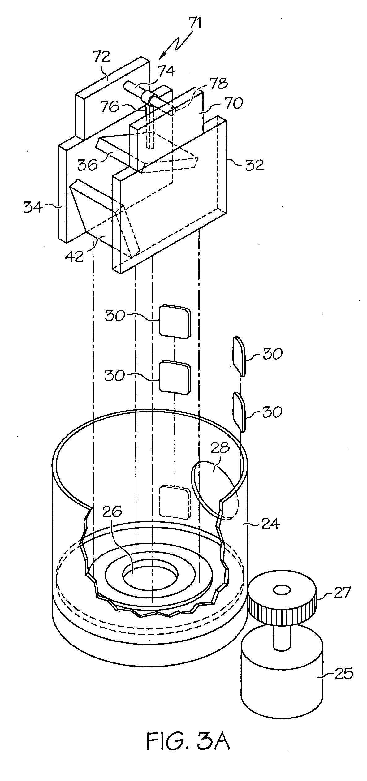
[0033]FIGS. 1-3 of the drawings illustrate a laser transmitter for projecting laser light according to the present invention. The transmitter projects a beam 12 outward, spinning the beam around a generally vertical axis. The beam defines a varying conical surface that is raised and lowered. As will be described in detail below, the beam may be cyclically raised and lowered while it spins so that it defines a reference conical surface of varying inclination. The beam inclination may be cyclically varied according to a schedule, it may be randomly varied, or it may be varied as needed to keep a receiver illuminated. For example, the beam may be kept aimed in a fixed azimuthal direction, raised and lowered, or directed to a particular deviation angle, as desired. The light defining the reference conical surface may have a very limited range of movement such that it does not move through a horizontal or generally horizontal orientation in which it is generally flat. Alternatively, the ...

second embodiment

[0041]FIGS. 4A and 4B show a transmitter constructed according to the present invention. Arrays of small mirrors, termed micro mirrors, have been developed for a number of different applications. Micro mirror arrays have been incorporated in high definition television systems, and in optical multiplexing and optical switching systems. Various array constructions are known in the art. “Magnetostrictive Micro Mirrors for an Optical Switch Matrix,” Lee et al, published in Sensors, October 2007, pages 2174-2182, describes a magnetostrictive arrangement for mirror actuation, while “A Two-Axis Electrothermal Micro Mirror for Biomedical Imaging,” 2003 IEEE / LEOS International Conference on Optical MEMS, August 2003, pages 14-15, describes a thermal actuation arrangement for micro mirrors. U.S. Pat. No. 7,354,167, issued Apr. 8, 2008, incorporated herein by reference, discloses micro mirror arrays that focus, deflect, and scan light beams, in which the mirrors are moved electrostatically or ...


PUM


Abstract

A laser transmitter projects a beam of laser light outward while raising and lowering the beam. The beam may define a conical surface of varying inclination. The transmitter includes a laser source that directs a beam generally vertically, and a beam diverting element. The beam diverting element is positioned in the path of the beam, intercepting the beam and redirecting it. The beam emerges from the transmitter as a non-vertical beam that is raised and lowered. The diverting element may include a pair of mirrors configured as a pentaprism, with one of the mirrors pivotable. Alternatively, the diverting element may include a plurality of micro mirrors. Also, the diverting element may include a conical reflector and an annular lens which is cyclically raised and lowered. The beam may be raised and lowered cyclically according to a predetermined schedule, or it may be raised and lowered non-cyclically.

Description

CROSS-REFERENCE TO RELATED APPLICATION[0001]Not applicable.STATEMENT REGARDING FEDERALLY SPONSORED RESEARCH OR DEVELOPMENT[0002]Not applicable.BACKGROUND OF THE INVENTION[0003]The present invention relates to a laser transmitter and to a method of operating a laser transmitter. Laser transmitters have been used in a variety of ways in the construction and surveying industries. In a typical application at a construction site, a laser transmitter projects a plane of laser light for use as a position reference by workers, and by various machines carrying laser receivers. The machines may be operated by workers who view position displays, or may be operated automatically or semi-automatically by control systems that respond to the measured positions and elevations, and to a database of desired positions and elevations. The machines may also carry other position detection devices, such as GPS receivers or the like, for supplementing or augmenting the laser system measurement of position....

Claims


Application Information

Patent Timeline
IPC IPC(8): H01S3/13G02B5/10G02B7/02
CPCG01C15/004G02B26/12G02B26/105G02B26/0875
Inventor TALBOT, NICHOLASJANKY, JAMESGOTTMAN, JAMES F.
Owner TRIMBLE NAVIGATION LTD
Why Eureka
Try Eureka