
Board Mounted Connector

Inactive Publication Date: 2009-12-10
MOLEX INC
View PDF2 Cites 19 Cited by
  • Summary
  • Abstract
  • Description
  • Claims
  • Application Information

AI Technical Summary

Benefits of technology

[0010]An object of the present invention is to solve the above-mentioned problems in the conventional board mounted connector and to provide a reliable board mounted connector which is configured such that the side surfaces of a housing do not project outward from the contour of the bottom surface of the housing when viewed from above, to thereby enable easy bonding of a tamper-proof cover having an opening to a circuit board and prevent formation of a gap between the opening of the tamper-proof cover and the lower edges of the side surfaces of the housing.
[0017]In the board mounted connector according to the present invention, the side surfaces of the housing do not project outward from the contour of the bottom surface of the housing when viewed from above. Therefore, it becomes possible to easily bond a tamper-proof cover having an opening to a circuit board, and prevent formation of a gap between the opening of the tamper-proof cover and the lower edges of the side surfaces of the housing, whereby tamper proof reliability can be improved.

Problems solved by technology

To register false numbers, which can result in the receipt of illegal rewards, a game player can move a conductive probe into a clearance between the surface of the circuit board and the lower edges of the side surfaces of the connector mounted to the circuit board until the probe engages one or more terminals.
Instead it is a complicated shape which is more difficult to form.

Method used


Image

  • Board Mounted Connector
  • Board Mounted Connector
  • Board Mounted Connector

Examples


Embodiment Construction

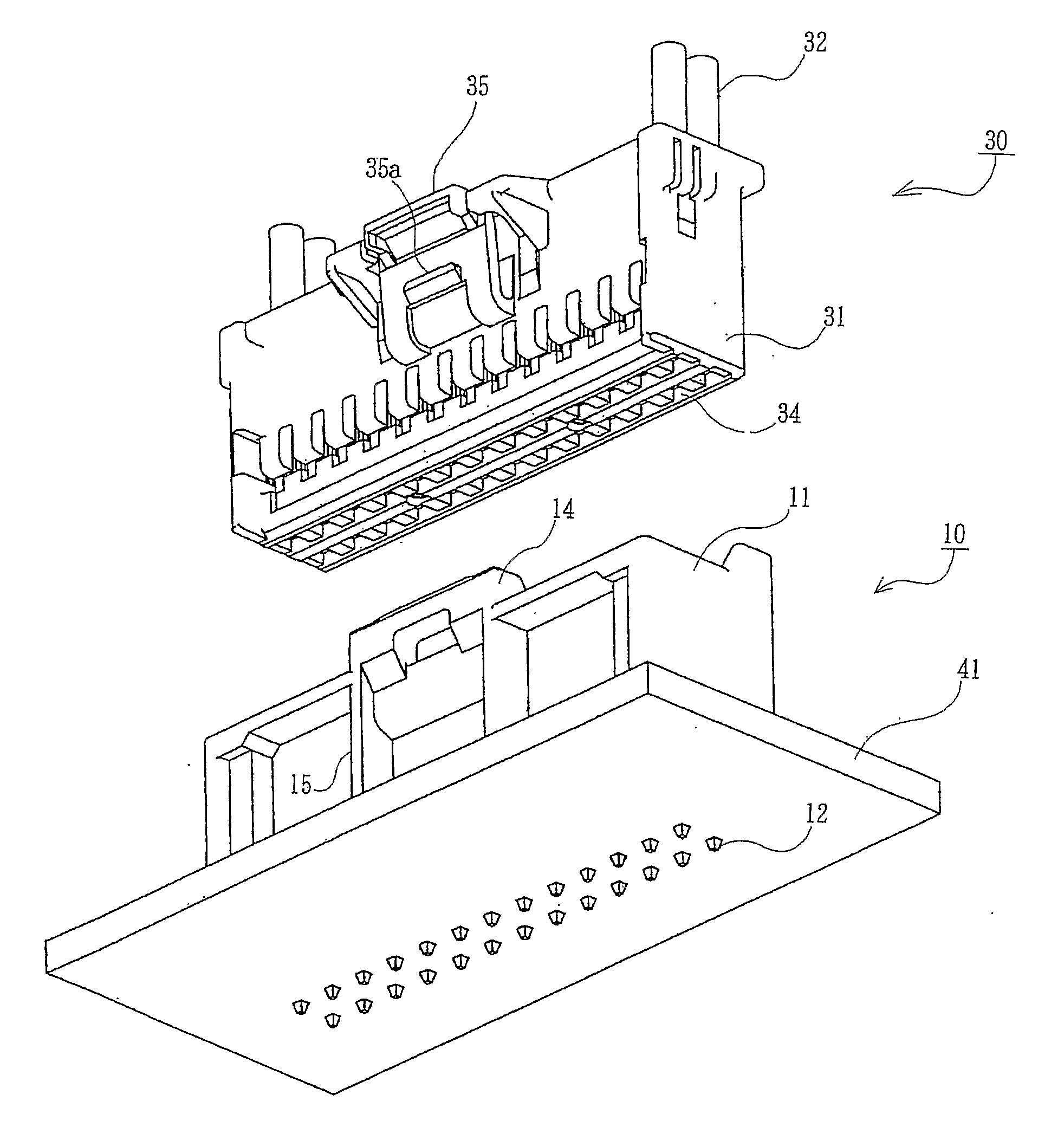
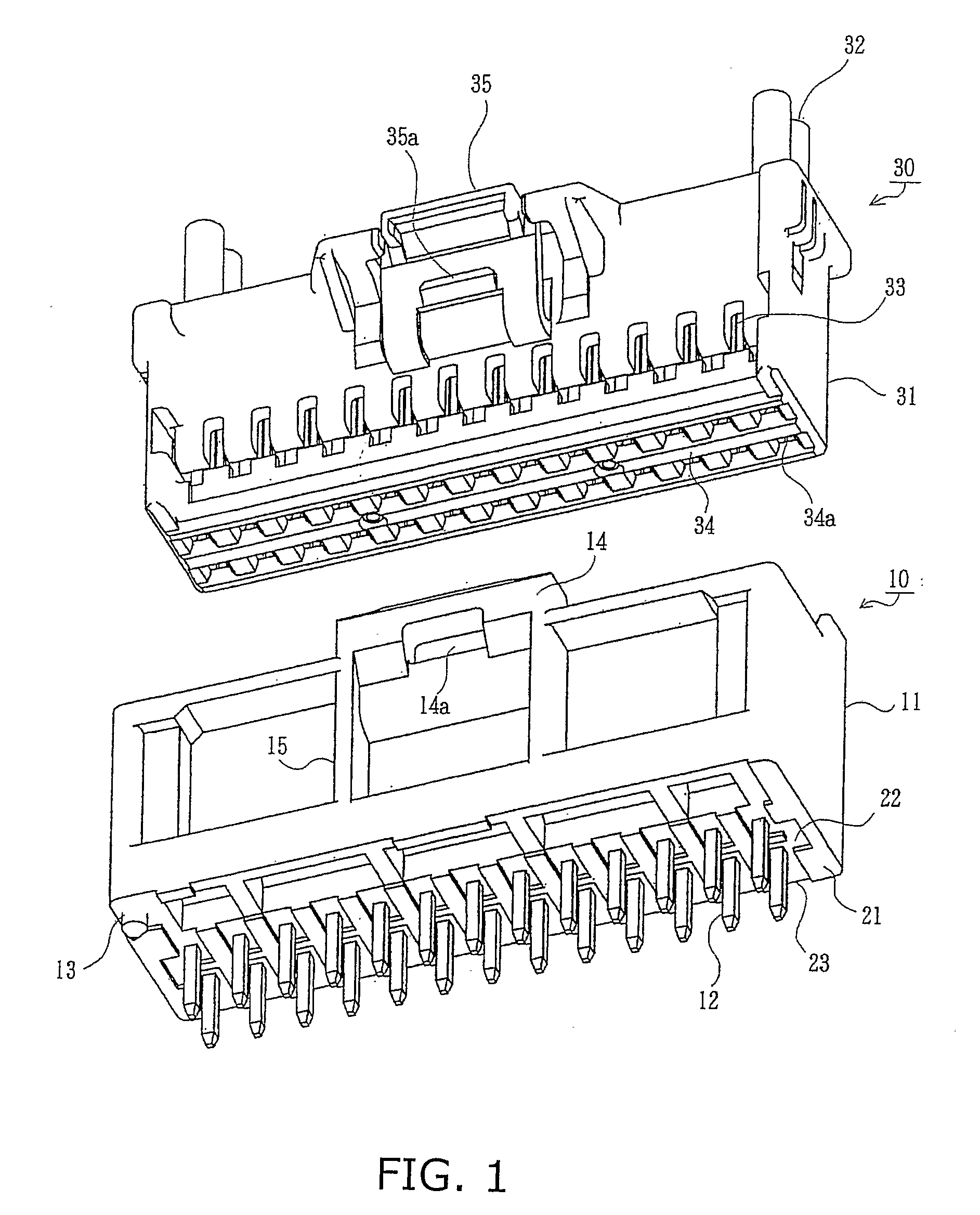
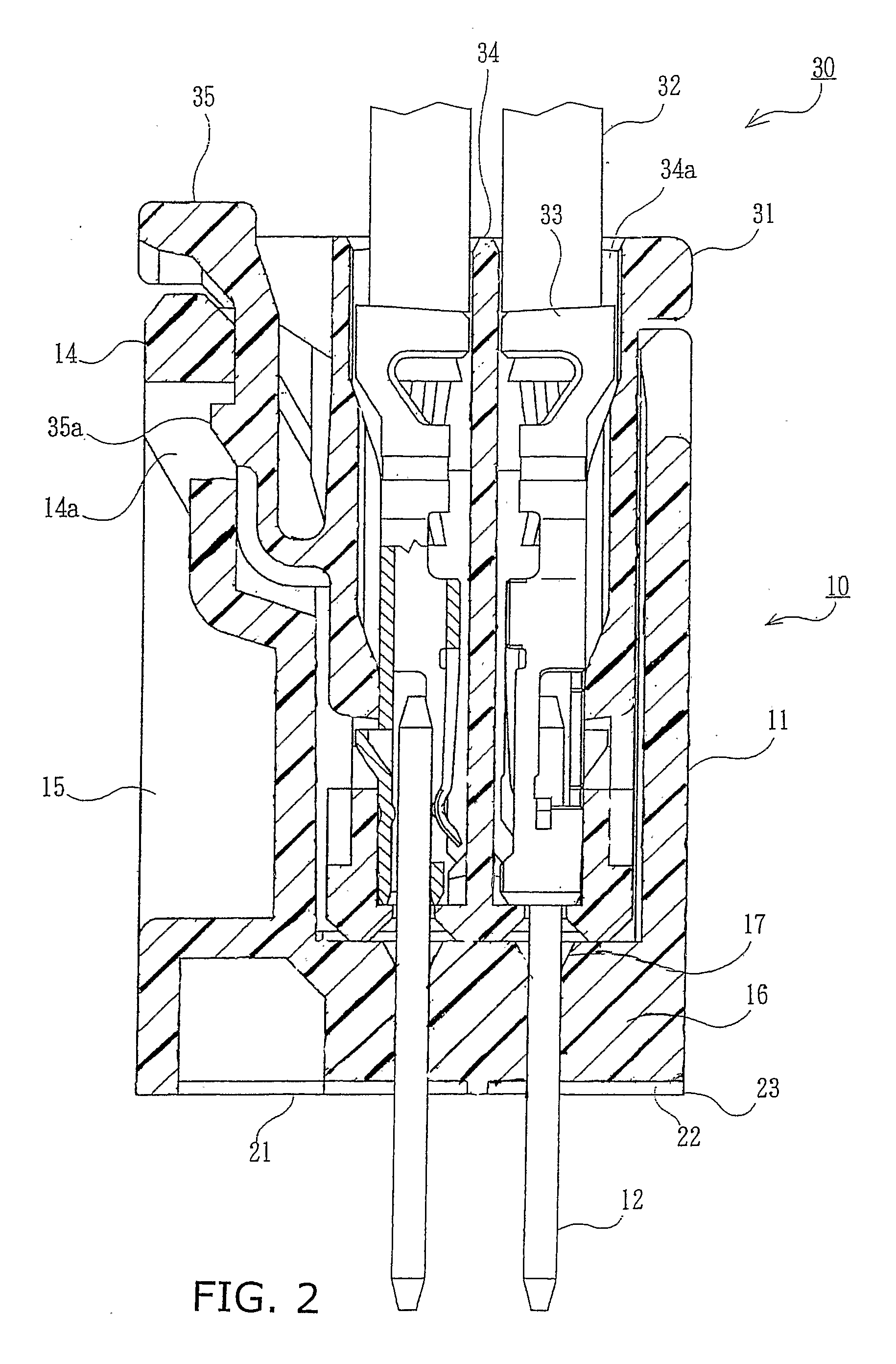
[0028]In FIGS. 1 and 2, reference numeral 30 denotes a counterpart connector, according to the present embodiment, which is used to electrically connect a cable including a plurality of wires 32 to a board mounted connector 10. The counterpart connector 30 may be used not only for connection of the illustrated cable which includes the wires 32 each having a circular cross section, but also for connection of a plate-shaped flexible cable such as a flexible flat cable (FFC) or flexible printed circuit (FPC). In the present embodiment, terms for expressing direction, such as up, down, left, right, front, and rear, are used for explaining the structure and action of respective portions of the board mounted connector 10 and the counterpart connector 30. However, these terms represent respective directions in the orientation shown in the drawings of the board mounted connector 10 and the counterpart connector 30.

[0029]The board mounted connector 10 is a receptacle connector, and includes ...


PUM


Abstract

A board mounted connector designed to have side surfaces forming a generally rectangular cross section so that a board mounted cover with a generally rectangular inner opening can easily slip over the connector housing. The connector has a housing having a bottom surface facing the circuit board, two end surfaces and two side surfaces extending upwardly from the peripheral edge of the bottom surface, the end and side surfaces forming planes which extend from the peripheral edge of the bottom surface to be perpendicular to the bottom surface. The end and side surfaces defining a peripheral wall with upper and lower portions all of which are located within the planes extending from the peripheral edge of the bottom surface.

Description

BACKGROUND OF THE INVENTION[0001]1. Field of the Invention[0002]The present invention relates to a board mounted connector.[0003]2. Description of the Related Art[0004]Many board mounted connectors have been used to connect a cable to a circuit board. FIG. 8 is a perspective view of such a connector and a mating cable connector. This connector appears in the Japanese Patent Application Laid-Open (kokai) No. 2000-123912). The reference numeral 301 in FIG. 8 denotes a circuit board having conductive traces (not shown) formed thereon, and a board mounted connector 302. A cable connector 304, which is connected to end portions of a plurality of parallel wires 303, is inserted into the board mounted connector 302. The board mounted connector 302 includes a housing 305 formed into a generally parallelepiped shape from an insulating material such as synthetic resin and a plurality of terminals 306 disposed in parallel within the housing 305. The terminals 306 pass through the bottom wall o...

Claims


Application Information

Patent Timeline
IPC IPC(8): H01R12/00
CPCH01R13/447H01R13/4538H01R12/79H01R12/716H01R13/6272
Inventor ITO, NAOTOSHIASAKAWA, KAZUSHIGE
Owner MOLEX INC
Learn More