
Electrochemical device

Inactive Publication Date: 2006-06-29
TDK CORPARATION
View PDF5 Cites 4 Cited by
  • Summary
  • Abstract
  • Description
  • Claims
  • Application Information

AI Technical Summary

Benefits of technology

[0005] In view of the problem mentioned above, it is an object of the present invention to provide an electrochemical device in which crimped parts are harder to peel off even when container materials are made thinner.
[0007] Since the gasket bonds the end part of one container member to the end part of the other container member in the electrochemical device in accordance with this aspect of the present invention, the end part of one container member, which is a crimped part, is harder to peel off. This makes it easier to keep the sealing performance in the electrochemical device even when the container members are made thinner.
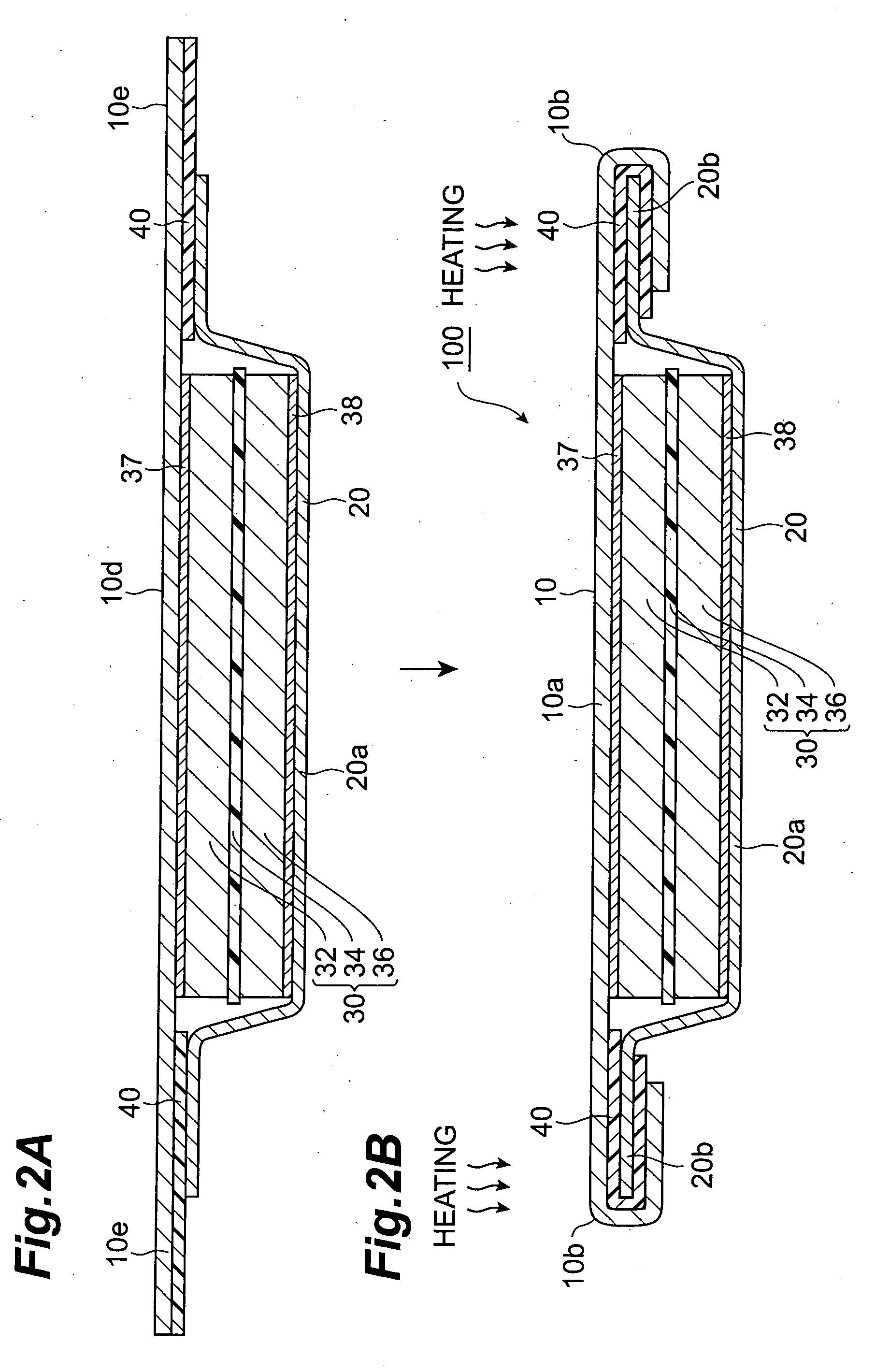
[0009] This can easily bond the end part of one container member and the end part of the other container member to each other by heating the gasket after crimping.
[0010] Preferably, one container member and the other container member are bonded to each other by heating the gasket after causing the end part of one container member to crimp the end part of the other container member. This facilitates the bonding operation.
[0012] In the electrochemical device in accordance with this aspect of the present invention, the end part of one container member, which is a crimped part, is protected by the resin part, so as to become harder to peel off. This makes it easier to keep the sealing performance in the electrochemical device even when the container members and lid members are made thinner.

Problems solved by technology

When the upper and lower lid materials are made thinner, however, the upper and lower lids decrease their strength, whereby their crimped parts are more likely to peel off.

Method used


Image

  • Electrochemical device
  • Electrochemical device
  • Electrochemical device

Examples


first embodiment

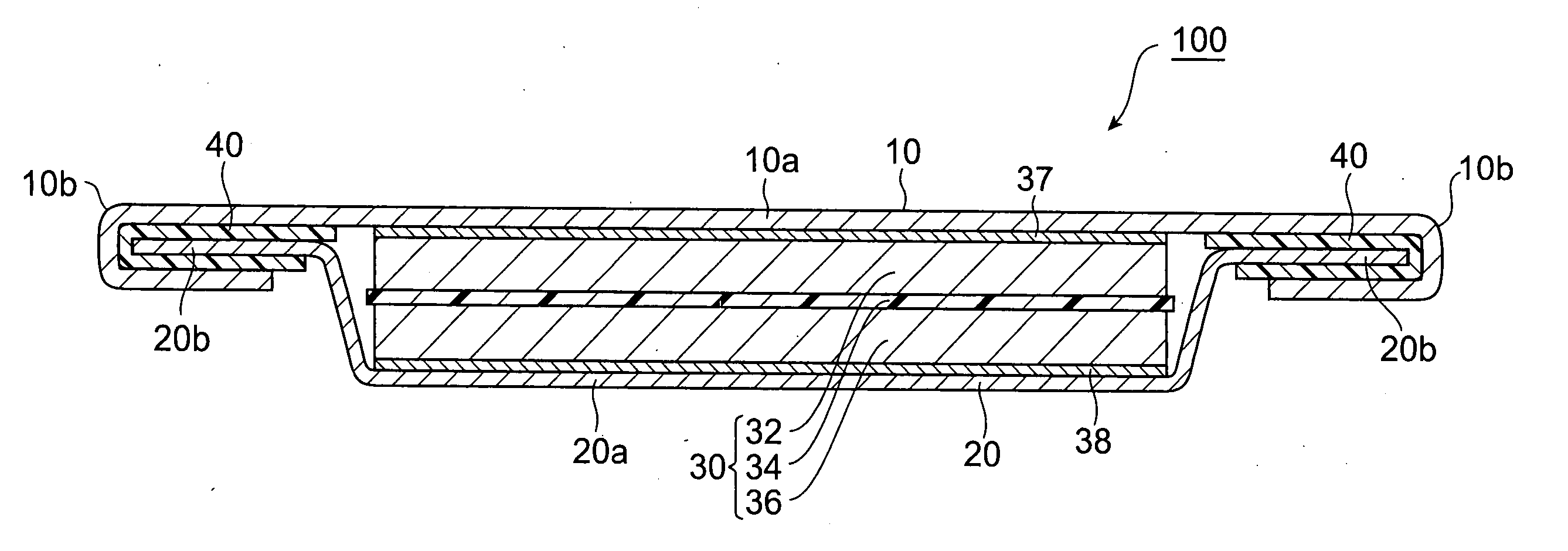
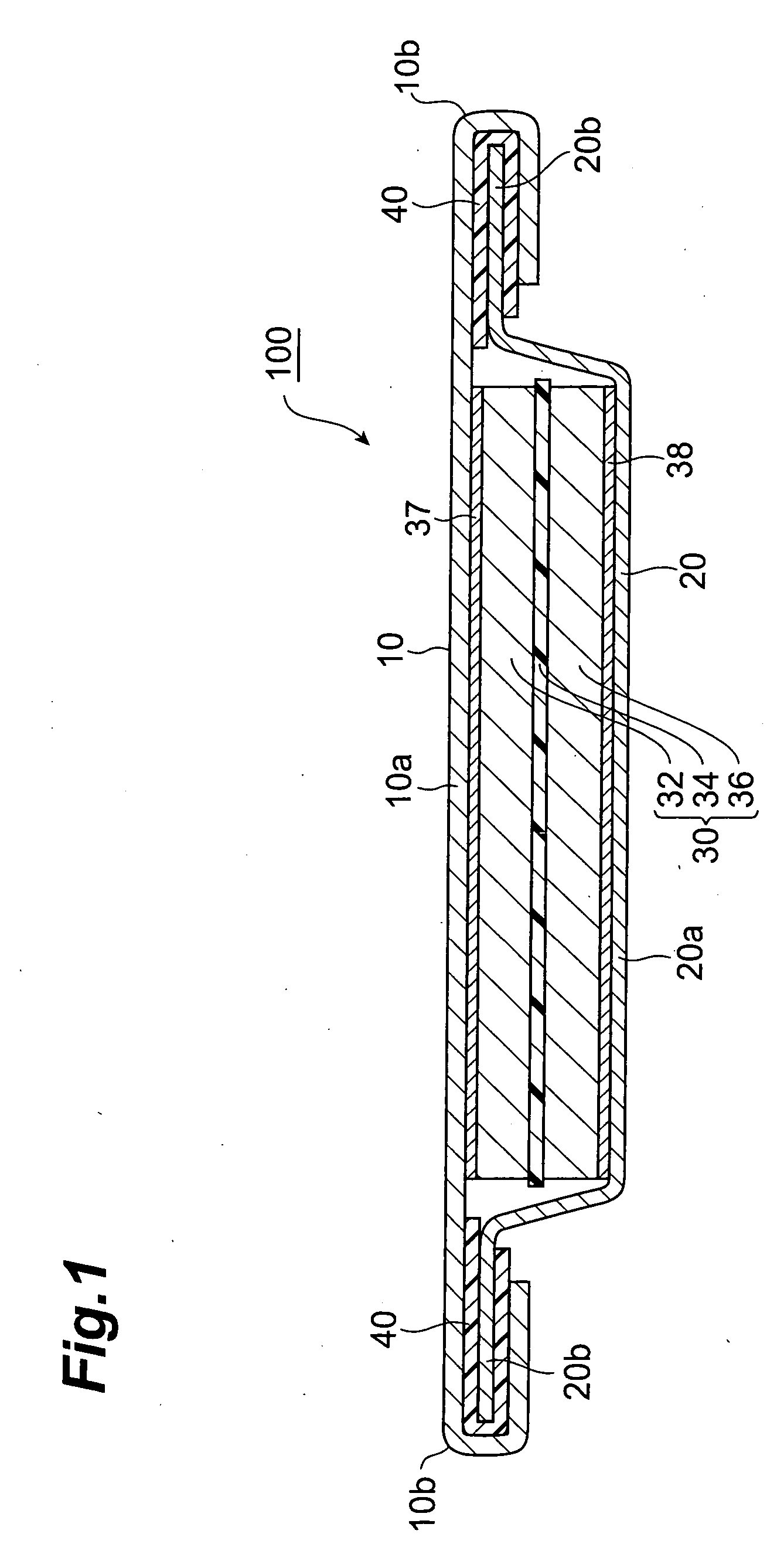
[0022]FIG. 1 shows a coin-type electric double layer capacitor 100 as the electrochemical device in accordance with an embodiment of the present invention.

[0023] This electric double layer capacitor 100 mainly comprises an electric double layer capacitor element (electrochemical element) 30, an upper lid (one container member) 10 and a lower lid (the other container member) 20 which act as container members for sealing the electric double layer capacitor element 30 by holding it from the upper and lower sides, and a gasket 40 for electrically insulating the upper lid 10 and lower lid 20 from each other.

[0024] The electric double layer capacitor element 30 mainly comprises a planar separator 34, and an anode (electrode layer) 32 and a cathode (electrode layer) 36 which oppose each other by way of the separator 34 interposed therebetween.

[0025] Each of the anode 32 and cathode 36 comprises an electronically conductive porous body and an electrolytic solution contained therein. Exam...

second embodiment

[0041] A coin-type electric double layer capacitor 200 as the electrochemical device in accordance with a second embodiment will now be explained with reference to FIG. 3. The electric double layer capacitor 200 in accordance with this embodiment differs from the first embodiment in that it further comprises an electrically insulative resin part 90 bonded from the end part 10b of the upper lid 10 to the lower lid 20 so as to cover a joint 99 between the upper lid 10 and lower lid 20.

[0042] Such a resin part 90 is easily obtained by applying an adhesive such as epoxy resin, for example.

[0043] This makes the end part of the crimping part 10b of the upper lid 10 harder to peel off than in the first embodiment.

[0044] Forming such a resin part 90 is advantageous when mounting the electric double layer capacitor 200 onto the substrate 210 by using reflow soldering parts 215, 216 as shown in FIG. 4.

[0045] First, the reflow soldering part 216 is provided between the lower face of the lo...

examples 1-1 to 1-5

[0051] First, an aluminum foil having a thickness of 80 μm was punched out into a circular form, so as to be used as an upper lid. Subsequently, a similar aluminum foil was punched out into a circular form and then was drawn, so as to form a cylindrical part and a brim, thus yielding a lower lid. Next, an electric double layer capacitor element having a thickness of 350 μm was prepared.

[0052] This electric double layer capacitor element was one in which a positive electrode, a separator, and a negative electrode were laminated in this order, the positive and negative electrodes were made of porous activated carbon, the separator was a porous resin, and they contained an electrolytic solution made of a propylene solution containing 1.8 mol / L of triethylmethylammonium tetrafluoroborate.

[0053] After accommodating the electric double layer capacitor element into the lower lid, the upper lid was overlaid thereon with an annular gasket made of acid-denatured polyethylene interposed ther...


PUM


Abstract

In an electric double layer capacitor 100 comprising an electrochemical element 30 including a pair of electrode layers 32, 36; a pair of container members 10, 20 made of a metal surrounding the electrochemical element 30; and an electrically insulative gasket 40, interposed between the pair of container members 10, 20, for electrically insulating the container members 10, 20 from each other; the electrochemical element 30 is sealed by causing a crimping part 10bof one container member 10 to crimp a brim 20b of the other container member 20 while interposing the gasket 40 between the crimping part 10b of one container member 10 and the brim 20b of the other container member 20, whereas the crimping part 10b of one container member 10 and the brim 20b of the other container member 20 are bonded to each other by the gasket 40.

Description

TECHNICAL FIELD [0001] The present invention relates to an electrochemical device in which an electrochemical element having a pair of electrode layers is sealed within a container. BACKGROUND ART [0002] Electrochemical devices of so-called coin type or button type, in which an electrochemical element having a pair of electrode layers is sealed within a thin cylindrical container, such as coin batteries, have been known. The container in such a coin-type electrochemical device includes a lower lid for accommodating an electrochemical element and an upper lid for sealing the lower lid, for example. With a gasket interposed between the lower and upper lids, an end part of the upper lid is bent, so as to crimp an end part of the lower lid by holding it from the outside, thus sealing the electrochemical element. [0003] In the coin-type electrochemical devices currently used in general, each of the upper and lower lid materials has a thickness of 200 to 300 μm. DISCLOSURE OF THE INVENTIO...

Claims


Application Information

Patent Timeline
IPC IPC(8): H01M2/08H01M2/02H01G9/10H01G11/42H01G11/78H01G11/80H01G11/82H01G11/84H01M50/119H01M50/186H01M50/193
CPCH01G9/016H01G9/10H01G9/155H01G11/80H01M2/0222H01M2/0285H01M2/08Y02E60/13Y02E60/10H01G11/74H01M50/109H01G11/82H01G11/78H01M50/186H01M50/193H01M50/119
Inventor TAKAHASHI, TETSUYAMIYAKI, YOUSUKEKOSUDA, ATSUKOOHTSUKA, MASAYUKIMIYABARA, KUNIO
Owner TDK CORPARATION
Learn More