
Airbag jacket for a vehicle rider

Inactive Publication Date: 2008-07-31
HONDA MOTOR CO LTD
View PDF4 Cites 36 Cited by
  • Summary
  • Abstract
  • Description
  • Claims
  • Application Information

AI Technical Summary

Benefits of technology

[0020]According to the present invention, the airbag body includes the flat front piece and the flat back piece joined together by sewing or bonding; each of the flat front and back pieces having a through hole formed therein through which a rider can pass his or her head through; at least a back covering portion, a shoulder covering portion, and a front covering portion formed continuously within in the airbag body; the inflator provided in the back covering portion. According to the present invention, gas from the inflator (during its activation) flows from the back covering portion to the front covering portion via the shoulder covering portion to fill these continuously formed portions. Hence, the airbag body can be quickly filled with gas, and sewing and bonding to be performed can be made easy.
[0021]Since the airbag body is shaped to be laterally symmetrical when worn, sewing and boding to be p

Problems solved by technology

In such configurations, installing one or more of hoses in the airbag body to secure one or more of gas passages increases the number of components required.
Moreover, in the existing airbag bodies including, for example, turned-back portions have complicated three-dimensional shapes.
Producing such airbag bodies, therefore, involves three-dimensional sewing which complicate sewing and bonding processes.

Method used


Image

  • Airbag jacket for a vehicle rider
  • Airbag jacket for a vehicle rider
  • Airbag jacket for a vehicle rider

Examples


first embodiment

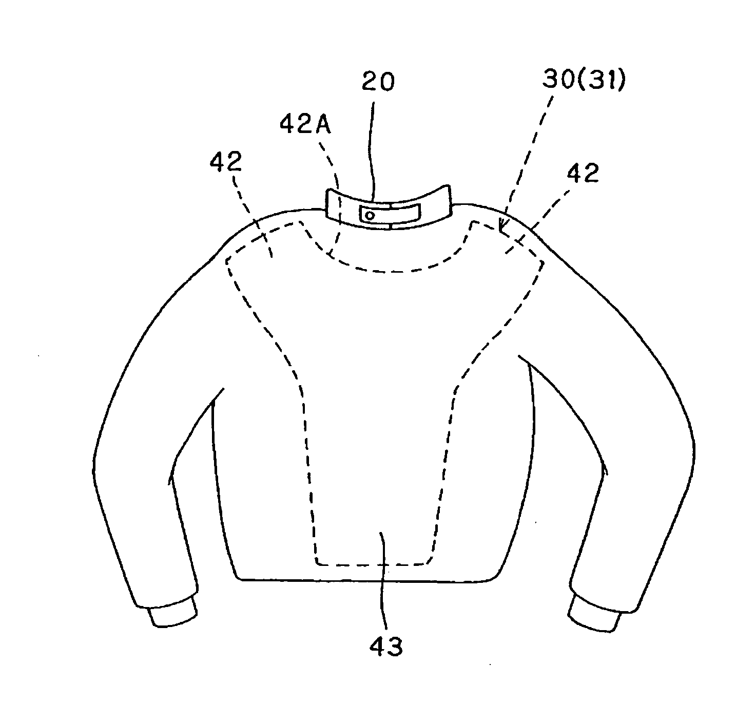
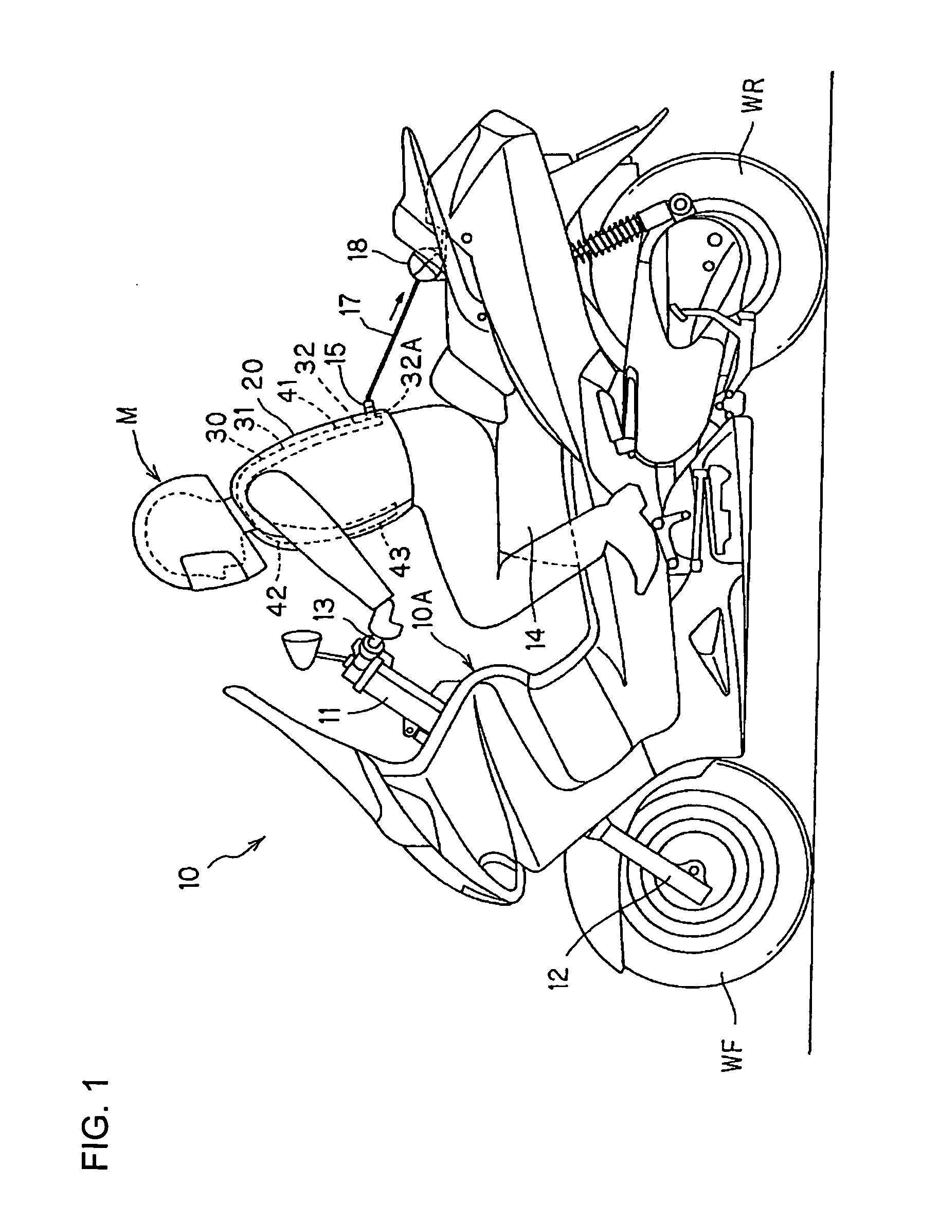
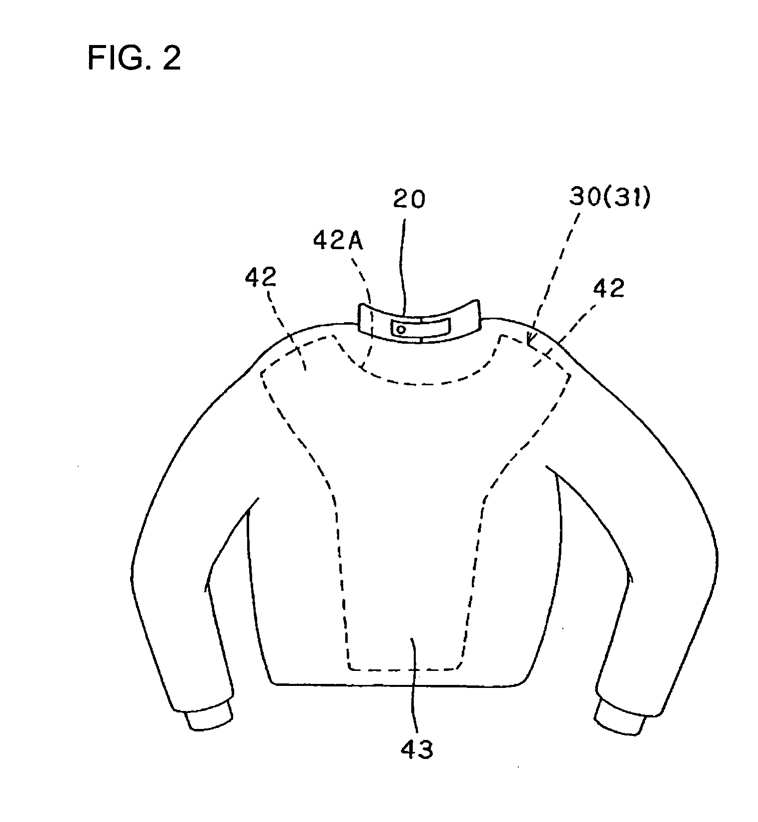
[0046]FIG. 1 shows a motorcycle rider M, riding a motorcycle 10, and wearing an airbag jacket 30 fitted with a rider jacket 20 according to a first embodiment of the present invention.

[0047]As shown in FIG. 1, the motorcycle 10 has a head pipe 11 in a front end portion of a body frame 10A (also referred as a body). The head pipe 11 steerably supports a front fork 12 to which a front wheel WF is journaled. A steering handlebar 13 is attached to an upper portion of the front fork 12. A rear wheel WR which is driven by an engine is suspended in a rear portion of the body frame 10A. A seat 14 is provided at the top of an intermediate portion, in the front-rear direction, of the body frame 10A.

[0048]The rider M wearing the rider jacket 20 sits on the seat 14. As shown in FIG. 2, the airbag jacket 30 is fitted with the rider jacket 20.

[0049]The airbag jacket 30 functions as a wearable airbag system for providing safety to the ride of the vehicle during collision, accidents, etc. The airba...

second embodiment

[0076]FIGS. 5 and 6 show a second embodiment of the present invention. As shown in these FIGS. 5 and 6, the airbag body 31 according to the second embodiment includes a discontinuous portion 45 (also referred as a gap 45) formed in one of the shoulder covering portion, for example a left shoulder covering portion 42L, so that the airbag body 31 is side-gapped when worn by the user.

[0077]In the following description of the second embodiment, features of the present invention, which are similar to those used in the first embodiment, are denoted by the same symbols as used for the first embodiment, and their description is omitted. Features which are different from those used in the first embodiment are described in detail.

[0078]As shown in FIG. 5, the rider jacket 20 in which the airbag jacket 30 is fitted in is configured to side fastening with a fastener line 25 provided on a left side (as viewed by the rider M) wearing the rider jacket 20. The airbag body 31 of the airbag jacket 30...

third embodiment

[0084]FIGS. 7 and 8 show a third embodiment of the present invention. In the third embodiment, the airbag body 31 includes a vertical discontinuous portion 46 formed in a front portion thereof, i.e., when worn by the rider, the airbag body 31 is vertically front-gapped in front portion (front covering portion 43) thereof.

[0085]In the following description of the third embodiment, features of present invention which are substantially same as those used in the foregoing embodiments are denoted by the same symbols as used for the foregoing embodiments, and their description is omitted. The inventive features which different from those used in the foregoing embodiments are described in detail.

[0086]As shown in FIG. 7, the rider jacket 20 in which the airbag jacket 30 is fitted in is shaped and / or configured for front fastening with the fastener line 25 extending substantially centrally and vertically in a front portion of the rider jacket 20. As shown in FIG. 8, the airbag body 31 inclu...


PUM


Abstract

An airbag jacket, to be fitted in a rider jacket, includes an airbag body configured to fill with gas from an inflator operatively connected with the airbag body. The airbag body includes a flat front piece, a flat back piece substantially identical to the flat front piece; the flat front and back pieces having an opening formed therein for permitting an user of the airbag jacket to pass his or her head therethrough. The flat front and back pieces are joined together along a peripheral boundary thereof and along a peripheral boundary of the opening by sewing or bonding so as provide a plurality of continuously formed body covering portions including at least a back covering portion, a shoulder covering portion and a front covering portion.

Description

CROSS-REFERENCE TO RELATED APPLICATIONS[0001]The present application claims priority under 35 USC §119 based on Japanese patent application No. 2007-021563, filed on Jan. 31, 2007. The entire subject matter of this priority document is herein incorporated by reference.BACKGROUND OF THE INVENTION[0002]1. Field of the Invention[0003]The present invention relates to an airbag jacket for a rider of a saddle-type vehicle such as a motorcycle, three-wheeler or all-terrain vehicle (ATV). More particularly, the present invention relates to an airbag jacket, fitted with a rider jacket worn by the vehicle rider, and having a plurality of continuously formed body covering portions formed by joining a plurality of substantially flat members.[0004]2. Description of the Background Art[0005]There are known airbag systems having an airbag body and an inflator fitted with clothing (e.g., a jacket) worn by a rider of a vehicle, e.g., a motorcycle. In such airbag systems, the airbag body is inflated, ...

Claims


Application Information

Patent Timeline
IPC IPC(8): A41D13/015
CPCA41D13/018Y10S2/03
Inventor ORITA, MASAYOSHIGOTO, HIROSHIKOBAYASHI, YUKIKIKUCHI, HIROYUKI
Owner HONDA MOTOR CO LTD
Learn More