Marking instrument
- Summary
- Abstract
- Description
- Claims
- Application Information
AI Technical Summary
Benefits of technology
Problems solved by technology
Method used
Image
Examples
first embodiment
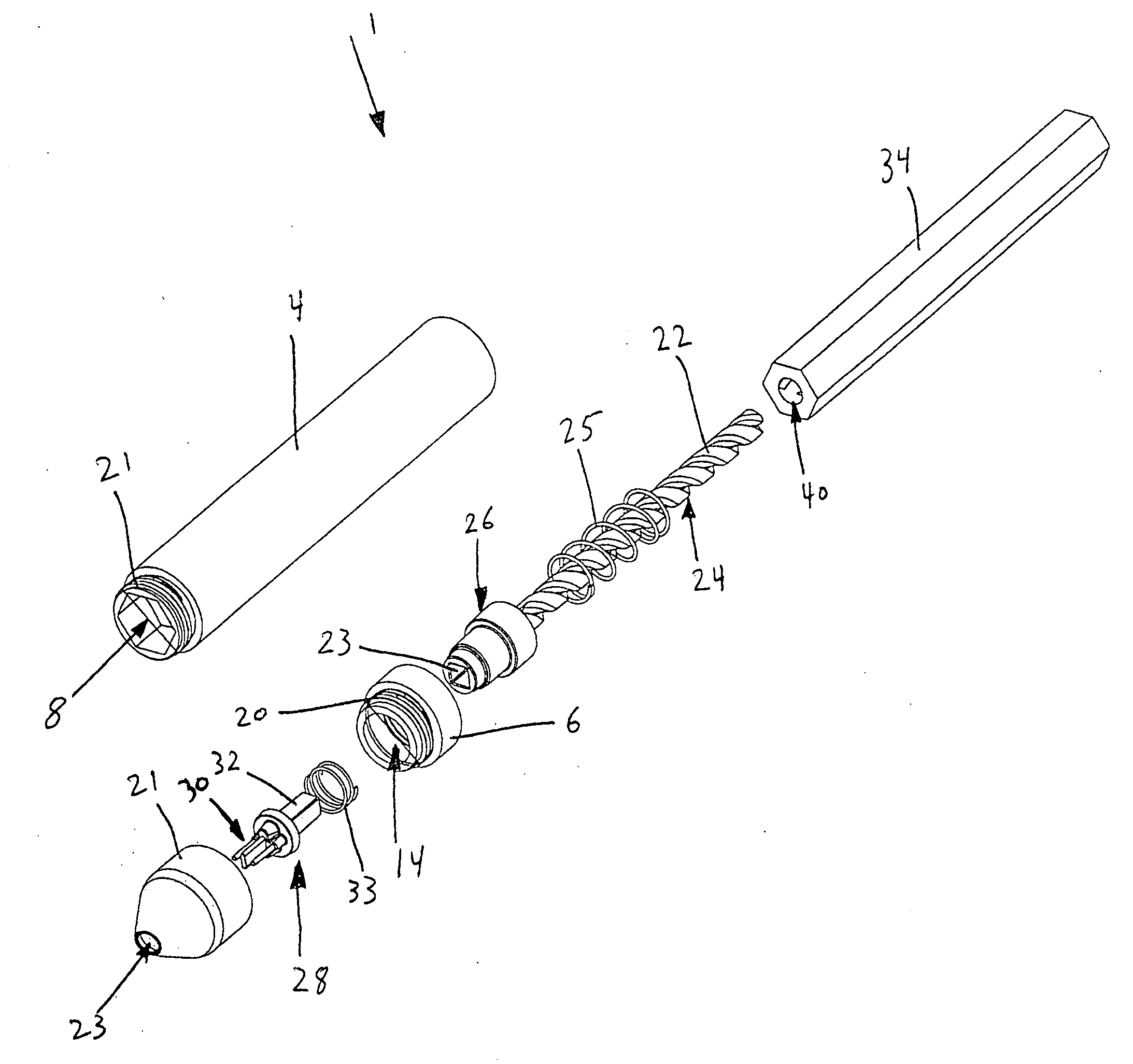
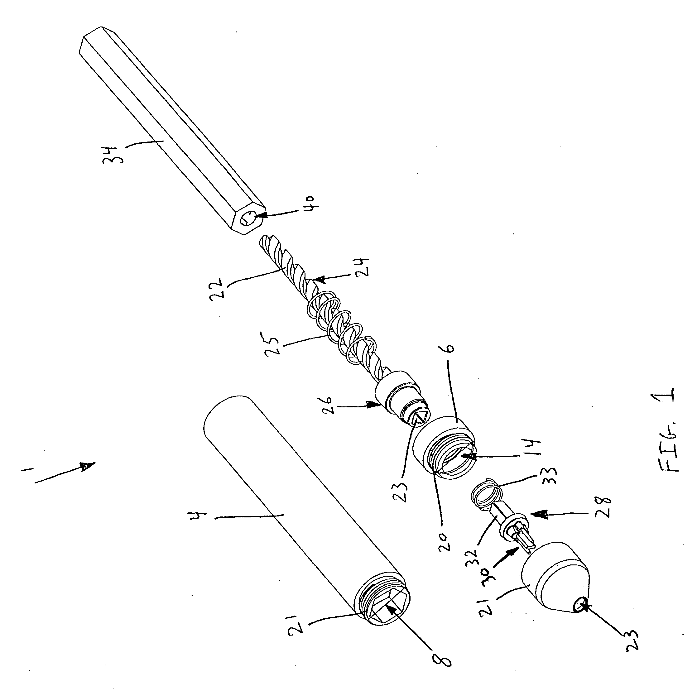
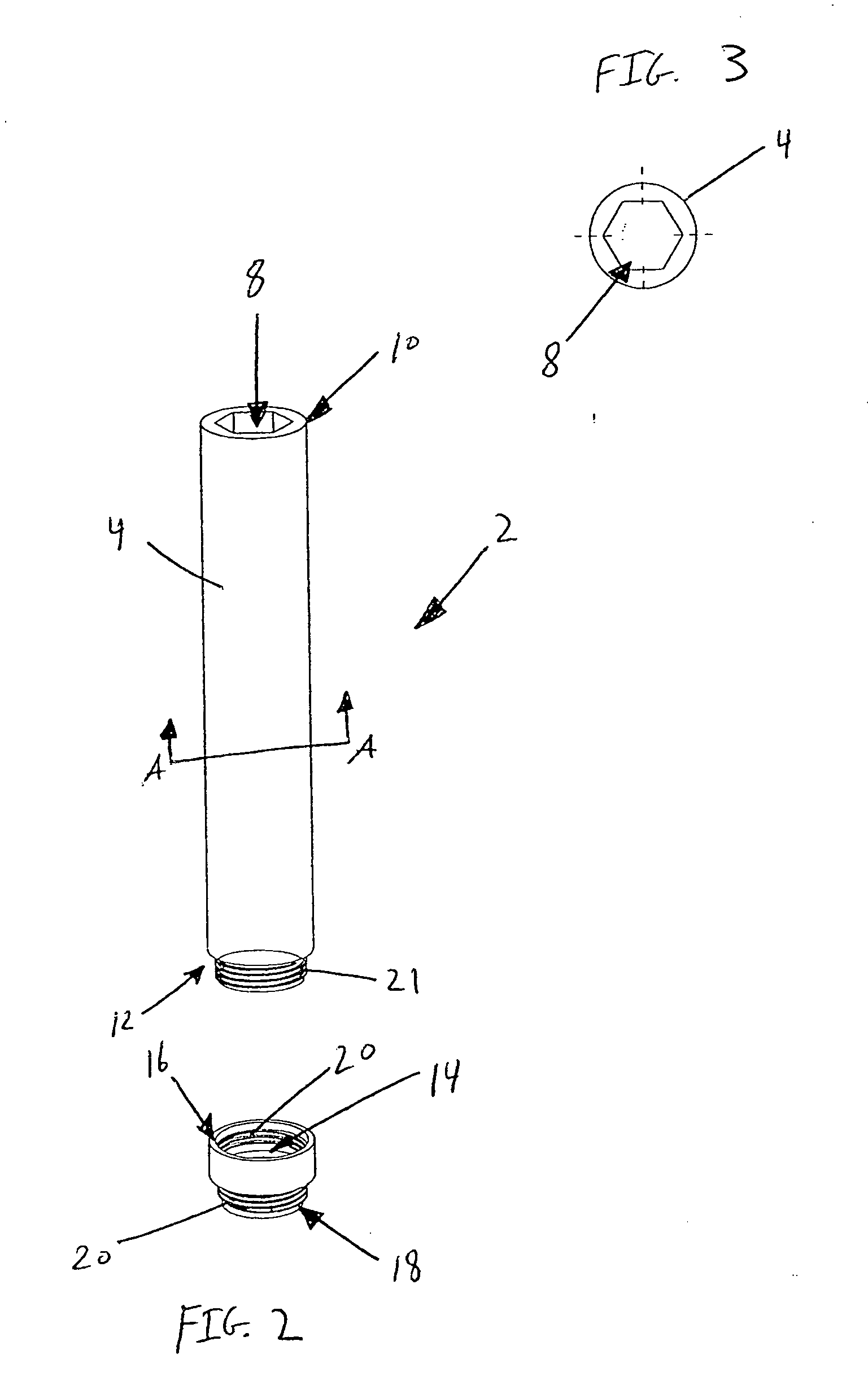
[0099]Turning now to the figures, in the instant invention depicted in FIGS. 1 and 2, the marking instrument 1 comprises a main body portion 2 that includes an upper body portion 4 and a lower body portion 6. As can be seen in FIGS. 1, 2 and 3 where FIG. 3 is a cross-sectional view about the line A-A in FIG. 2, the upper body portion 4 has a hexagonal internal cavity 8 that extends along the entire length of the upper body portion 4, from the top end 10 to the bottom end 12. As will be described below, the cross-sectional shape of the internal cavity 8 can be of numerous geometries. The lower body portion 6 also includes a hollow internal cavity 14 that extends from the top end 16 to the bottom end 18 of the lower body portion 6. The cross-sectional shape of the internal cavity 14 of the lower body portion 6 is circular. Additionally, the lower body portion 6 includes threads 20 at both its top 16 and bottom 18 ends. To assemble the upper body portion 4 and the lower body portion 6,...
second embodiment
[0112]the instant invention will now be discussed. As depicted in FIGS. 10, 11, 12A and 12B, a marking instrument 99 according to this embodiment comprises a circular body portion 100 having a hollow internal cavity 102. FIG. 12B is a cross-sectional view of a marking instrument constructed according to the instant embodiment, taken about the line A-A in FIG. 12A. Disposed within internal cavity 102 is a depressor element 104 that sits on a first spring or depressor spring 106. As depicted in FIGS. 14, 15A and 15B, where FIG. 15B is a cross-sectional view about the line E-E in FIG. 15A, the depressor element 104 includes an internal cavity 114. The internal cavity 114 can be any shape, but preferably, it is circular. The depressor element 104 also includes a plurality of elongate slots 115 that extend from a bottom end 117 of the depressor element 104 part way up the side of the depressor element 104. Further, disposed on the depressor element 104 is rotation restricting element 105...
third embodiment
[0124]In the instant invention, instead of a user physically depressing a depressor element to mechanically rotate the marking platform, an electric motor is used to rotate the marking platform. As depicted in FIGS. 22, 23, 24A and 24B, a marking instrument 200 according to this embodiment comprises a circular body portion 202 having an internal cavity 203. FIG. 24B is a cross-sectional view about line A-A in FIG. 24A, which is an assembled marking instrument according to the instant embodiment. Within the internal cavity 203 is a battery compartment 204 for a battery 205. Disposed beneath the battery compartment 204 towards the bottom end 206 of the body portion 202 is an electric motor 208. Connected to the drive shaft 209 of the electric motor is a circular drum 210. As depicted in FIGS. 22, 25A and 25B, the bottom portion 212 of the drum 210 includes a keyed portion 214. FIG. 25B is a cross-sectional view about the line B-B of the drum 210 depicted in FIG. 25A. As can be seen in...
PUM
 Abstract
Description
Claims
Application Information
 - R&D
- Intellectual Property
- Life Sciences
- Materials
- Tech Scout
- Unparalleled Data Quality
- Higher Quality Content
- 60% Fewer Hallucinations
Browse by: Latest US Patents, China's latest patents, Technical Efficacy Thesaurus, Application Domain, Technology Topic, Popular Technical Reports.
© 2025 PatSnap. All rights reserved.Legal|Privacy policy|Modern Slavery Act Transparency Statement|Sitemap|About US| Contact US: help@patsnap.com


