
Weight sensing

Active Publication Date: 2017-03-09
CARDE CHRIS
View PDF9 Cites 10 Cited by
  • Summary
  • Abstract
  • Description
  • Claims
  • Application Information

AI Technical Summary

Benefits of technology

The patent describes a weight sensor that can be used under a bed or other support members that may not be centred over the sensor. The sensor is mounted with a tripod arrangement that allows it to self-centre when a load is applied. This design is particularly useful when using a weight sensor under a bed with different types of bed legs. The sensor is connected to a data hub which stores only the recorded weight data, and can be connected to an external server for further processing of the data. This design helps to minimize the amount of data stored and allows for easy transfer to an external server for further analysis.

Problems solved by technology

However if the user forgets to weigh themself then data is missed and the history of their weight is incomplete.
However, a simple weight measuring process using weight sensors positioned under the legs of a bed is only able to give a single weight reading for the whole bed.
Such a system therefore has limitations for multiple bed users.
There are a number of typical low profile weight sensors or load cells in the prior art, although not especially designed for use as bed scales.
However the loads encountered beneath a centre leg of a double bed could rise to 150 kg or more and this type of load cell would need to be excessively thick to accommodate such high loads.
The various load cells known in the prior art have not been adapted for use in weight sensors intended to bear the weight of bed and be sensitive to changes in weight e.g. when a person moves in their sleep.
Moreover it has not previously been possible to independently monitor the weight and weight shifting of two people sharing the same bed.

Method used


Image

  • Weight sensing
  • Weight sensing
  • Weight sensing

Examples


Embodiment Construction

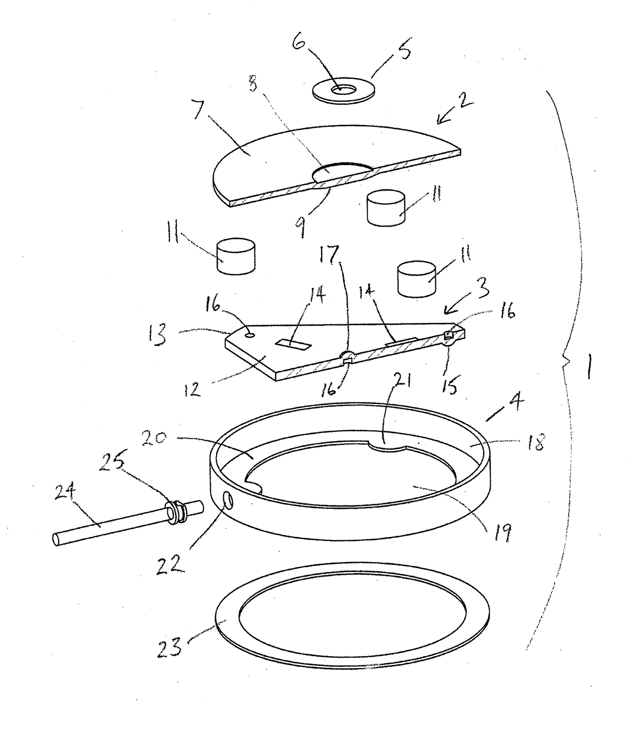
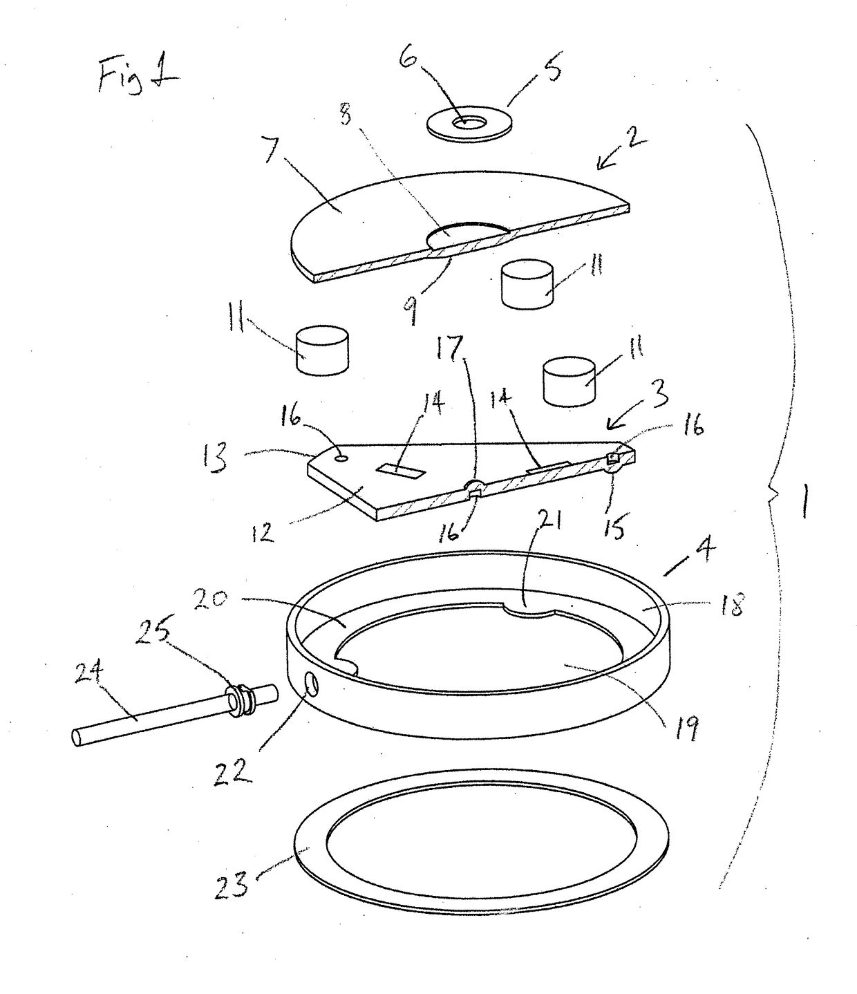
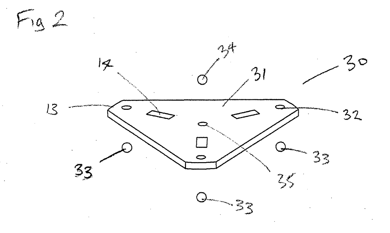
[0070]Referring to FIG. 1 there is shown an exploded perspective view of a sensor pad 1 consisting of an upper platform 2 mounted over a load cell 3 and a base 4. The base 4 has a bottom 19, side wall 18, an optional bearing surface 20 with optional mounting pads 21 and a cable cut-out 22. An optionally truncated triangular plate 12 (shown as a half section) with an apex bump 15 at each of three apexes 13 on a bottom surface of the plate 12, one or more strain gauges 14 mounted to either the top, bottom or both surfaces of plate 12, a central bump 17 on a top surface of the plate 12 and optional bump recesses 16 to aid the formation of the bumps 15, 17, can be placed into the base 4 so that the three apex bumps 15 rest on the bearing surface 20, or optionally directly on the bottom 19, such that the load cell 3 sits in a stable manner by virtue of having three points of contact.

[0071]The platform 2 consists of a top disc 7 with an optional upper recess 8, and an optional thickened s...


PUM


Abstract

A weight sensor may include a weighing platform and a load cell coupled to the platform to sense a weight applied to the platform, the load cell may include a deformable plate with one or more strain gauges arranged to provide an electrical signal representing the weight applied to the platform, and a base supporting the load cell, wherein the deformable plate is movably mounted to the base at only three contact points, the contact points allowing lateral movement of the plate when the plate deforms in response to a weight applied to the platform. The weight sensor makes it possible to monitor the weight and weight shifting of two people sharing the bed. The weight sensor is self-centering when a load is applied off-center to the platform, which is beneficial when used underneath a bed, e.g., under a bed leg or other support member which may not be aligned.

Description

RELATED APPLICATIONS[0001]The present application is a continuation-in-part of U.S. Ser. No. 14 / 513,248, filed on Oct. 14, 2014, now allowed. U.S. Ser. No. 14 / 513,248 is incorporated herein by reference in full.TECHNICAL FIELD[0002]The present invention relates to a weight sensor suitable for use under a bed and to a weight sensing system for a bed.BACKGROUND OF THE INVENTION[0003]A bathroom weighing scale is a commonly used piece of apparatus that allows a user to weigh themself to track their weight. Typically a user will weigh themself at the same time each day, for example when they wake up and enter the bathroom in the morning. Advanced bathroom scales are available that connect, via WiFi, to the internet and allow a user's weight to be remotely logged. The user can then review how their weight has varied over a period of time. However if the user forgets to weigh themself then data is missed and the history of their weight is incomplete.[0004]It is known that a weight sensing ...

Claims


Application Information

Patent Timeline
IPC IPC(8): G01G19/52G01G19/44
CPCG01G19/445G01G19/52G01G3/1402G01G3/141G01G21/23A61G2203/44A61G7/0527G01L1/044G01L1/2206
Inventor GOUGH, JULIANKALOGROULIS, ALEXANDERPETHICA, RALPHDURA, PATRICK
Owner CARDE CHRIS
Learn More