Multi-group transmission of a motor vehicle
- Summary
- Abstract
- Description
- Claims
- Application Information
AI Technical Summary
Benefits of technology
Problems solved by technology
Method used
Image
Examples
Embodiment Construction
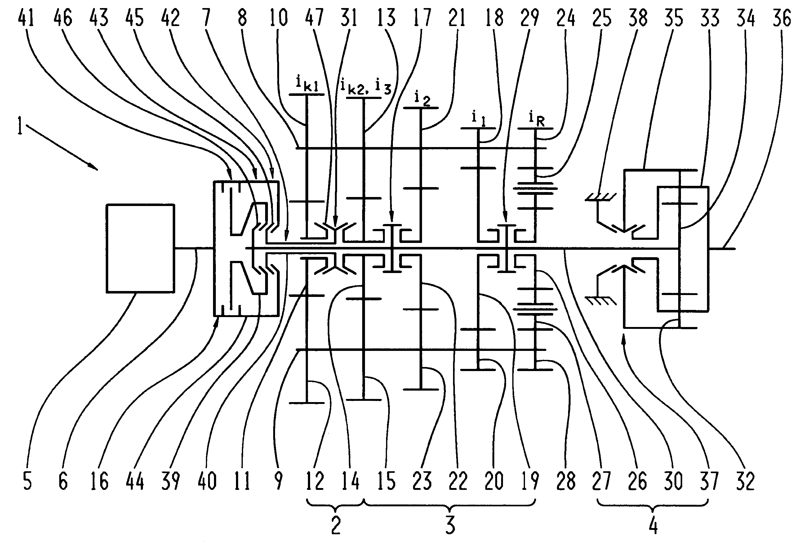
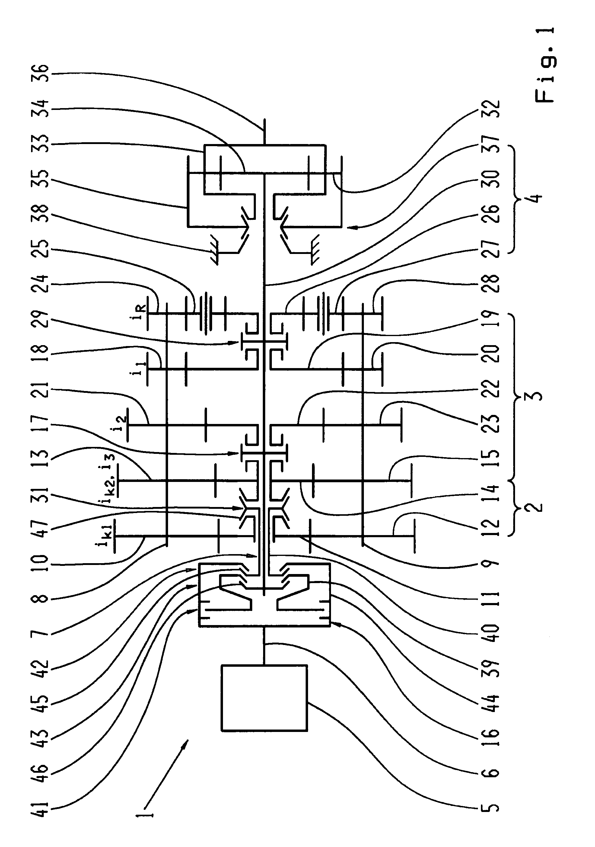
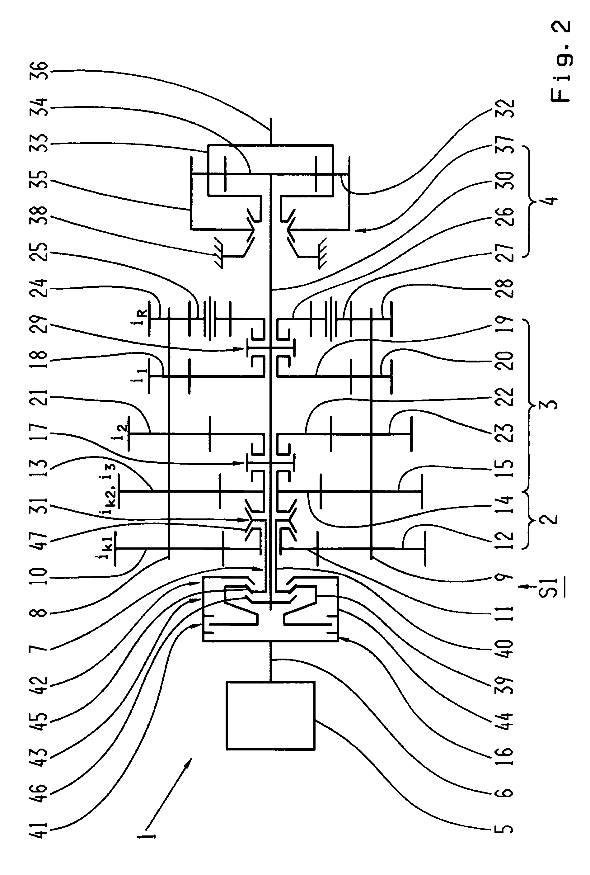
[0040]FIG. 1 shows an automated multi-group transmission which is made as a two-countershaft transmission 1 with two rotating countershafts 8, 9 mounted parallel to one another and three transmission groups 2, 3 and 4 arranged one after another, as can be provided for example in the drivetrain of a utility vehicle. Such a transmission per se, i.e. without traction force support, is known from the ZF-AS Tronic series produced by the present applicant, and with traction force support, from DE 10 2006 024 370 A1 by the present applicant, mentioned at the start.
[0041]The first transmission group 2, arranged on the motor side, is made as a two-gear splitter transmission. The second, central transmission group 3 is formed by a three-gear main or basic transmission. As the third transmission group 4 on the drive output side is arranged a downstream, two-gear range group.
[0042]The splitter group 2 has two constants ik1, ik2, respectively comprising fixed wheels 10, 12 and 13, 15 arranged in...
PUM
 Abstract
Description
Claims
Application Information
 - R&D
- Intellectual Property
- Life Sciences
- Materials
- Tech Scout
- Unparalleled Data Quality
- Higher Quality Content
- 60% Fewer Hallucinations
Browse by: Latest US Patents, China's latest patents, Technical Efficacy Thesaurus, Application Domain, Technology Topic, Popular Technical Reports.
© 2025 PatSnap. All rights reserved.Legal|Privacy policy|Modern Slavery Act Transparency Statement|Sitemap|About US| Contact US: help@patsnap.com


