Assay Timing in a Clinical Analyzer Using a Cuvette Carrier

a technology of clinical analyzer and assay timing, which is applied in the field of sample analysis systems, can solve the problem that the assay protocol is limited to having a few distinct values

Active Publication Date: 2009-12-17
SIEMENS HEALTHCARE DIAGNOSTICS INC
View PDF5 Cites 16 Cited by
  • Summary
  • Abstract
  • Description
  • Claims
  • Application Information

AI Technical Summary

Problems solved by technology

This tie severely limits or prevents the clinical analyzer from providing any variation in incubation time for different assays and as a result, the assay protocols are limited to having a few distinct values for the incubation durations.

Method used


Image

  • Assay Timing in a Clinical Analyzer Using a Cuvette Carrier
  • Assay Timing in a Clinical Analyzer Using a Cuvette Carrier
  • Assay Timing in a Clinical Analyzer Using a Cuvette Carrier

Examples


Embodiment Construction

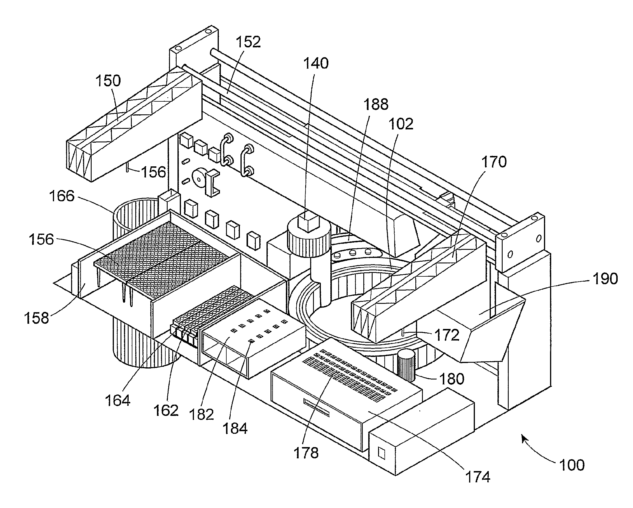
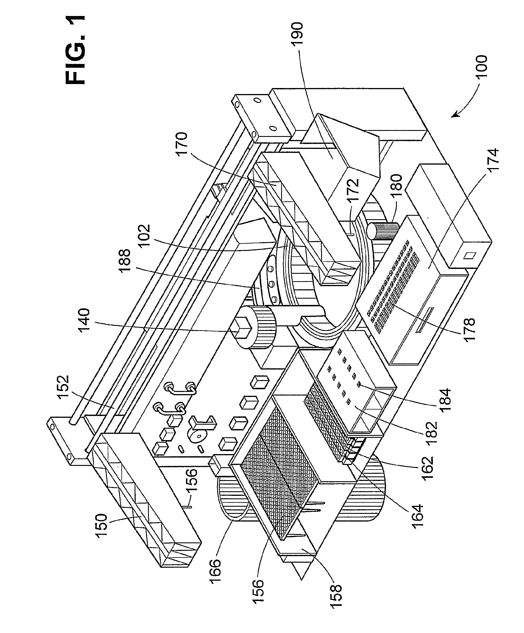
[0037]A clinical analyzer incorporating one embodiment of the invention is generally indicated by the reference number 100 in FIG. 1.

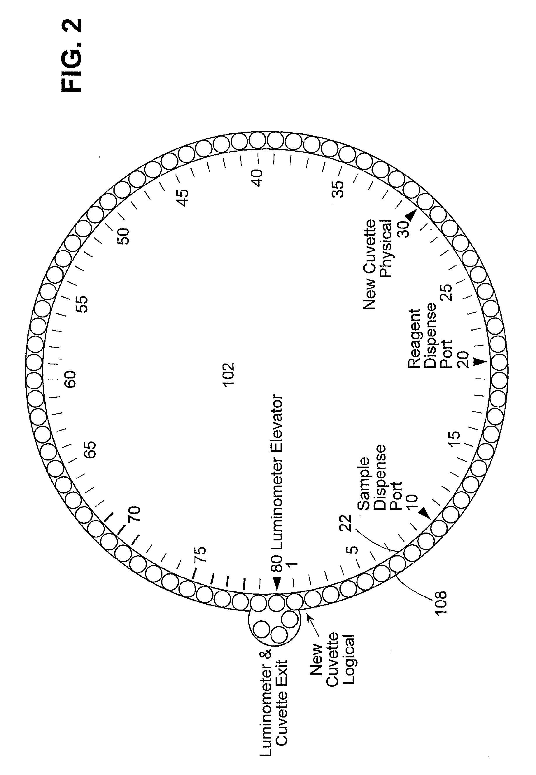
[0038]The clinical analyzer 100 includes a cuvette ring or reaction ring 102 of known construction shown in simplified schematic form in FIG. 2. The cuvette ring 102 is movable in a horizontal plane about a central vertical axis. Movement of the cuvette ring 102 can be activated in a known manner by a suitable known stepping motor (not shown) with a known drive wheel (not shown) pressed against the outer circumference of the cuvette ring 102.

[0039]The cuvette ring 102 (FIG. 2) includes eighty cuvette openings, spaces, or positions equally spaced one next to another around a peripheral portion of the ring, with each cuvette opening accommodating a removable and preferably disposable cuvette 108, shown in simplified form as a circle.

[0040]Equally spaced indicia lines with numbers at intervals of 1, 5, 10, 15, 20, 25, 30, 35, 40, 45, 50, 55, 60, 65, 70, 7...


PUM

PropertyMeasurementUnit
time durationaaaaaaaaaa
cyclic timeaaaaaaaaaa
timeaaaaaaaaaa

Abstract

The clinical analyzer includes a cuvette carrier that is moved in a manner to provide flexible assay timing and variable incubation periods. Multiple assays having such varied incubation times can be run concurrently in random-access, avoiding timing conflicts. Fluid delivery stations are placed around the cuvette carrier in positions that are independent of assay timing. The cuvettes move in unison, in multiples of incremental steps, along a closed geometrical path. The cuvette carrier is movable variable distances in opposite directions in a single time cycle to position specific cuvettes at specific locations for delivery of sample or reagent. The direction of movement of the cuvette carrier is preferably based on a determination of the shortest distance between the cuvette and respective fluid delivery stations. However, in each time cycle there is a net progressive incremental stepwise movement of the cuvettes in a selected direction.

Description

BACKGROUND OF THE INVENTION[0001]1. Field of the Invention[0002]This invention relates to sample analysis systems for automated clinical analysis of biological fluid samples and more particularly to an apparatus and method that uses discrete reaction cuvettes and allows simultaneous performance of assays of varied predetermined incubation periods of samples and reagents. Preferably the cuvettes in the clinical analyzer traverse a closed path, such as a circular path of a cuvette ring.[0003]2. Related Prior Art[0004]In one known clinical analyzer, cuvettes for receiving sample and reagent are positioned one behind another in a straight line. The cuvettes are moved along a straight path or track, in a single direction, in movement cycles of fixed time duration. The movement cycles are often referred to as machine cycles or time cycles, (or just cycles, when clearly construed from the context), such as, for example, twenty seconds as used in a known clinical analyzer.[0005]Each cuvette...

Claims


Application Information

Patent Timeline
Patent Type & Authority Applications(United States)
IPC IPC(8): G01N35/10
CPCG01N35/0092G01N35/0098G01N35/026G01N2035/0093G01N2035/0094
Inventor COHEN, BERI J.
Owner SIEMENS HEALTHCARE DIAGNOSTICS INC
Why Eureka
Try Eureka