Power transmission apparatus for press machine

a technology of power transmission apparatus and press machine, which is applied in the direction of press ram, manufacturing tools, gearing, etc., can solve the problems of increasing the time taken to store energy required to perform the next press operation, significant decrease in available energy, and inability to perform successive press operations at the desired spm, etc., to achieve simple and cost-efficient structure, easy to manufacture, and easy to implement in a small space

Inactive Publication Date: 2009-12-17
AIDA ENG LTD
View PDF3 Cites 0 Cited by
  • Summary
  • Abstract
  • Description
  • Claims
  • Application Information

AI Technical Summary

Benefits of technology

[0010]The present invention has been made in view of the above described situations and has as an object to provide a power transmission apparatus for press machine that can transmit rotation between a drive part and a driven part with predetermined switchable reduction gear ratios while having a simple, cost-efficient, and easy-to-manufacture structure that can be implemented in a small space.
[0020]The present invention can provide a power transmission apparatus for press machine that can switch the reduction gear ratio in rotation transmission between a driving part and a driven part among specific ratios, while the apparatus has a simple and cost-efficient structure that is easy to manufacture and easy to implement in a small space.

Problems solved by technology

If the reduction gear ratio is fixed, for example in the case where press working is performed using a rotation energy stored in a fly wheel, if the press working is performed at a speed in the low speed range (i.e. low strokes-per-minute (SPM) range) with a reduction gear ratio that is suitable for press working speeds in the high speed range (high SPM range), the time taken to store energy required to perform the next press operation increases gradually due to insufficient energy.
Thus, successive press operations cannot be performed at a desired SPM (this is because use of a reduction gear ratio suitable for the high speed range leads to a significant decrease in the available energy in the low speed range), and press working that requires high energy cannot be performed practically.
Machining of spline grooves 15, 16 provided on the outer circumference of the drive shaft 12 and the inner cylindrical portion of the sliding gear 19 for the spline engagement is not easy, and the use of the spline fitting leads to an increase in the machining cost and production cost, as a matter of fact.
This leads to a large rotational energy consumption at the time of starting the drive, and stopping of the rotation may be difficult.

Method used


Image

  • Power transmission apparatus for press machine
  • Power transmission apparatus for press machine
  • Power transmission apparatus for press machine

Examples


Embodiment Construction

[0026]In the following, an exemplary embodiment of the power transmission apparatus for press machine according to the present invention will be described with reference to the accompanying drawings. It should be understood that the present invention is not limited to the embodiment described below.

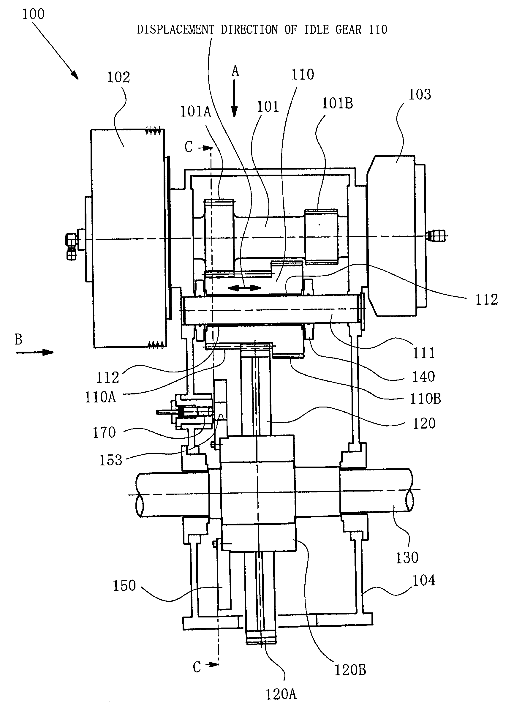
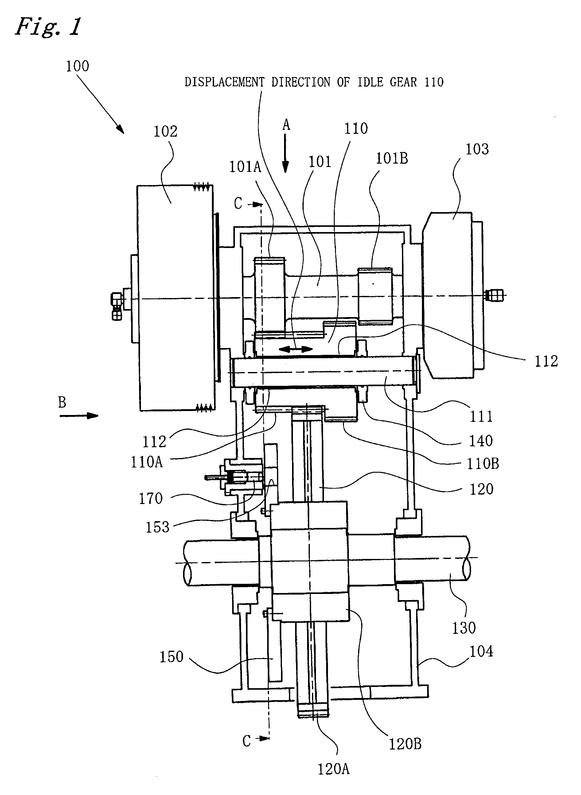
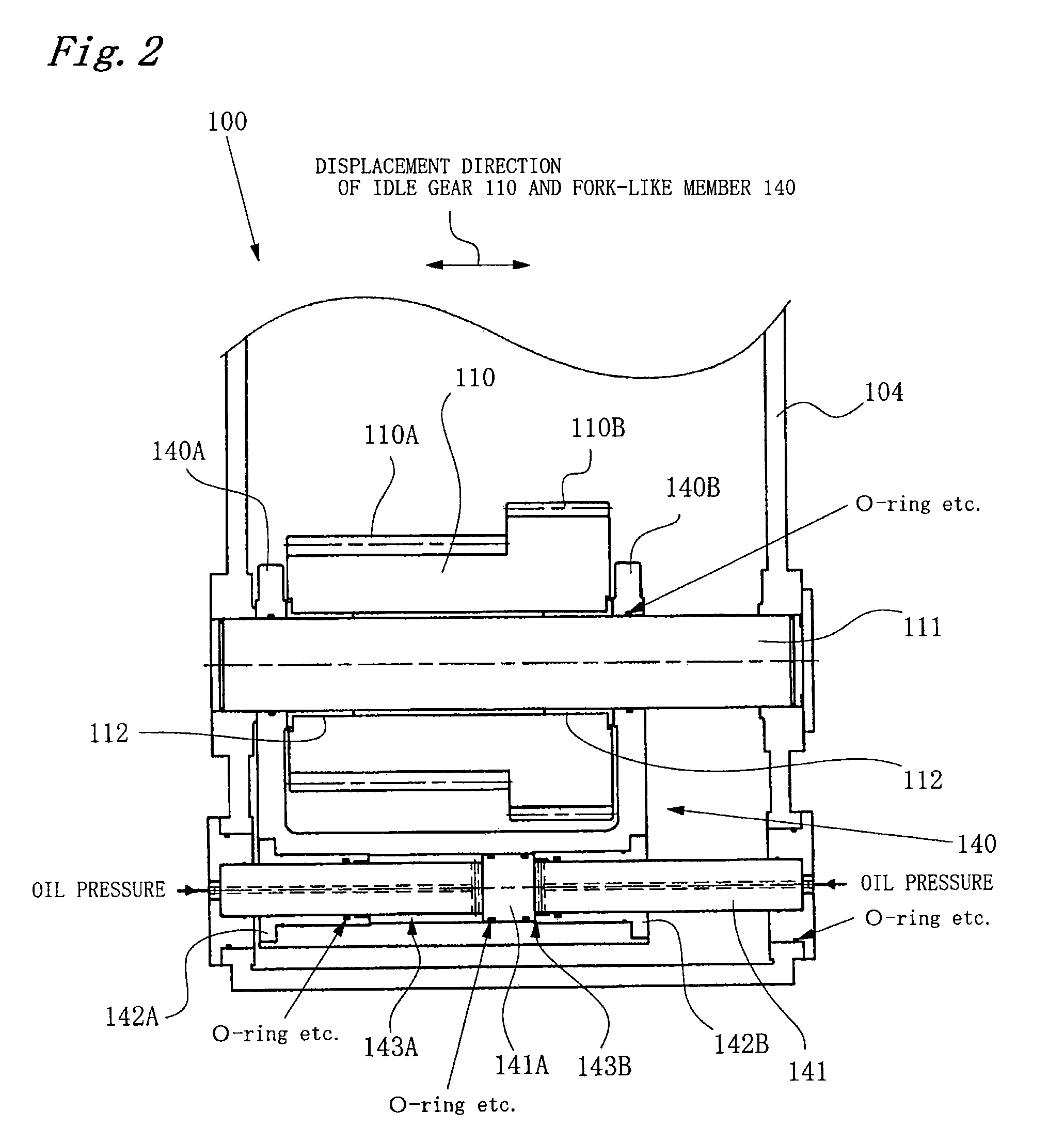
[0027]FIG. 1 is a front view of a power transmission apparatus 100 for press machine according to an embodiment. FIG. 1 shows portions relevant to the present invention, where some portions are cut away for illustration. FIG. 2 shows a fork-like member 140 that will be described later and the portions relevant thereto as seen from the direction indicated by arrow A in FIG. 1, for illustration of the structure of the fork-like member 140. FIG. 3 is a side view as seen from the direction indicated by arrow B in FIG. 1. FIG. 4 is a view taken along line C-C in FIG. 1.

[0028]On the left end (in FIG. 1) of a drive shaft 101 is attached a fly wheel 102 etc. The fly wheel 102 is rotationally driv...


PUM


Abstract

A power transmission apparatus for press machine according to the invention transmits rotational power from a drive shaft to a driven shaft. The apparatus has at least two drive gears arranged along an axial direction and substantially integrally attached to the drive shaft, a driven gear substantially integrally attached to the driven shaft, and an idle gear rotatably supported on an idle shaft and having a gear meshing with the driven gear and a plurality of gears corresponding respectively to the at least two drive gears. The idle gear can be displaced relative to the drive gear along the axial direction of the idle shaft to cause one of the at least two drive gears and corresponding one of the plurality of gears of the idle gear to mesh with each other selectively.

Description

CROSS-REFERENCE TO RELATED APPLICATION [0001]This application claims the benefit under 35 U.S.C. §119 of Japanese Patent Application No. 2008-155674, filed on Jun. 13, 2008, which is hereby incorporated by reference herein in its entirety.FIELD OF THE INVENTION [0002]The present invention relates to a power transmission apparatus for press machine, that is, for example, a power transmission apparatus that transmits rotation between a driving part (e.g. a fly wheel in which rotational energy is stored) and a driven part (e.g. a drive shaft for driving a slide) and can switch the reduction gear ratio (change gear ratio) among specific ratios.BACKGROUND [0003]A power transmission apparatus of this type is described in, for example, Japanese Utility Model Application Laid-Open No. S55-77600. As shown in FIG. 5, this apparatus has a sliding gear 19 having an inner cylindrical portion that is spline-fitted (with spline grooves 15 and 16) on the outer circumference of a drive shaft 12 so t...

Claims


Application Information

Patent Timeline
Patent Type & Authority Applications(United States)
IPC IPC(8): F16H3/08F16H63/02
CPCB30B1/266Y10T74/19219Y10T74/19251B30B15/14
Inventor MIZUNO, KAORUMAEDA, NOBUYOSHI
Owner AIDA ENG LTD
Why Eureka
Try Eureka