Modular Low-Clearance Centralizer and Method of Making Modular Low-Clearance Centralizer

a low-clearance centralizer and modular technology, applied in the direction of drilling pipes, drilling casings, borehole/well accessories, etc., can solve the problems of high cost of low-clearance bow spring centralizers cut from a unitary piece of tubular, increase the manufacturing cost of the centralizer, and time-consuming alternative methods, etc., to achieve efficient and inexpensive, the effect of reducing cos

Inactive Publication Date: 2009-12-17
FRANKS INT
View PDF33 Cites 18 Cited by
  • Summary
  • Abstract
  • Description
  • Claims
  • Application Information

AI Technical Summary

Benefits of technology

[0011]An embodiment of the present invention satisfies one or more of the above-stated needs. An embodiment of the invention provides an efficient and inexpensive method to make a low-clearance modular bow spring centralizer to center a tubular within a drilled borehole. A centralizer may be made at a lower cost according to an embodiment of the present invention, and may perform as well as a more expensive centralizer that is made from a unitary piece of tubular material. An embodiment of the invention provides a bow spring module that may be used to make a low-clearance centralizer.
[0013]It should be appreciated by those skilled in the art that the process of forming bow spring modules in this manner may be automated. It should be understood by those skilled in the art that the bow spring module produced in this manner may be shaped according to the corresponding shape of the male die and the female die cavity, and that a large number of generally identical bow spring modules may be inexpensively and / or rapidly produced.
[0014]It should be further understood that bow spring modules produced in this manner may be efficiently stacked and / or handled, and that the residual material stresses resulting from the cold working of a metal, e.g., low-carbon steel, plate material may be removed by heating the bow spring module for a period of time, and then by quenching the bow spring module, e.g., by immersion in water, to impart desired metallurgical resiliency to the metal, e.g., low-carbon steel material.
[0017]In an alternate embodiment, an apparatus may comprises a bow spring module comprising an elongate rib, a first collar segment at a first end of the rib and a second collar segment at a second end of the rib, each of the first and second collar segments having sides disposed generally laterally to the center of the collar segment aligned with the rib. In one embodiment, the apparatus may comprise beveled edges along the sides of the first collar segment and the second collar segment. The beveled edges may facilitate welding of a plurality of the first collar segments together to form a first centralizer collar and welding a plurality of second collar segments to form a second centralizer collar, each having a generally circular cross-section. In one embodiment, the beveled edges on the sides of the first and second collar segments may be formed during the steps of forming the first and second collar segments.

Problems solved by technology

Low-clearance bow spring centralizers cut from a unitary piece of tubular may be expensive to make.
These special tools can add substantially to the manufacturing cost of the centralizer.
The alternative method described is time consuming and may require post-fabrication heat treating and / or quenching to alleviate the heat-affected zones.
Conversely, a relatively low-weight tubular to be installed in a substantially vertical section of a borehole may require fewer bow springs to adequately center the tubular.

Method used


Image

  • Modular Low-Clearance Centralizer and Method of Making Modular Low-Clearance Centralizer
  • Modular Low-Clearance Centralizer and Method of Making Modular Low-Clearance Centralizer
  • Modular Low-Clearance Centralizer and Method of Making Modular Low-Clearance Centralizer

Examples


Embodiment Construction

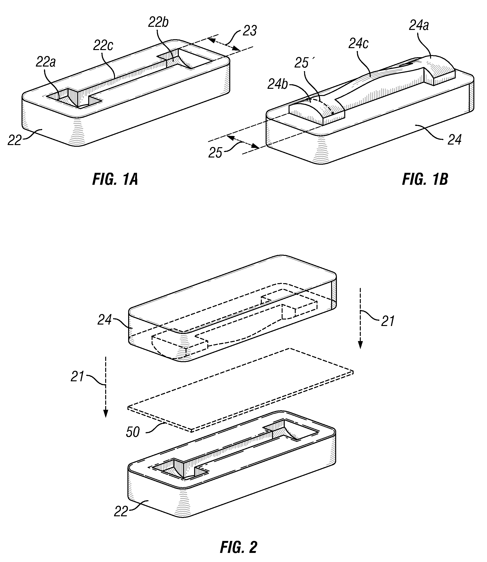
[0030]FIG. 1A is a perspective view of a female die cavity 22 that may be used to produce one embodiment of a bow spring module according to one embodiment of the invention. The die cavity of FIG. 1A comprises a first collar segment recess 22a, a second collar segment recess 22b, and a rib recess 22c connecting the first collar segment recess 22a to the second collar segment recess 22b. It should be understood that the first collar segment recess 22a and the second collar segment recess 22b may be generally identical, and each may comprise a uniformly curved bottom having a generally uniform radius of curvature, and the bottom may be recessed and / or surrounded by a generally vertical wall.

[0031]FIG. 1B is a perspective view of a male die 24 that may be used with the female die cavity of FIG. 1A to produce an embodiment of a bow spring module according to one embodiment of the invention. The male die 24 comprises a first collar segment protrusion 24a, a second collar segment protrusi...


PUM


Abstract

A low-clearance bow spring centralizer (10) can be made by providing a plurality of bow spring modules (54), each having an elongate rib (52) with a first integrally-formed collar segment (54) at a first end and a second integrally-formed collar segment (56) at a second end wherein the first collar segment (54) and the second collar segment (56) are joined to adjacent first and second collar segments, respectively. The bow spring modules may be interlinked by welding a seam (55) formed between abutting sides of adjacent pairs of first collar segments and / or second collar segments. The sides (54a) of the first collar segment and the sides (56a) of the second collar segment may each be perpendicular to the axis of the centralizer bore, and seams (55) therebetween may be welded to form a first centralizer collar and a second centralizer collar, coupled one to the other by the ribs (52).

Description

BACKGROUND OF THE INVENTION[0001]1. Field of the Invention[0002]This invention is directed to a low-clearance centralizer to center a tubular within a borehole, and to a low-cost method of making a modular low-clearance centralizer that can radially collapse to pass through a restriction, and that can deploy to generally center a tubular within a drilled borehole.[0003]2. Description of the Related Art[0004]Centralizers can be secured at spaced intervals along a tubular string to provide radial stand-off between the tubular and the wall of a drilled borehole in which the tubular is installed. Bow spring centralizers generally comprise a pair of aligned collars defining a bore therethrough to receive the tubular, and a plurality of angularly-spaced bow springs biased to provide stand-off. Bow spring centralizers may collapse to pass, e.g., along with the tubular, through restrictions, and to deploy to provide a generally uniform annulus between the exterior of the tubular and the wal...

Claims


Application Information

Patent Timeline
Patent Type & Authority Applications(United States)
IPC IPC(8): E21B19/24
CPCE21B17/1028
Inventor BUYTAERT, JEAN
Owner FRANKS INT
Why Eureka
Try Eureka