System and method for vertical moment connection

a moment connection and narrow gap technology, applied in the field of welding, can solve the problems of long and laborious process of either option, and achieve the effect of facilitating the speed of erecting a low-rise, facilitating moment connection, and making vertical moment connection welds much faster

Inactive Publication Date: 2009-12-17
BONG WILLIAM L
View PDF5 Cites 5 Cited by
  • Summary
  • Abstract
  • Description
  • Claims
  • Application Information

AI Technical Summary

Benefits of technology

[0010]When erecting high-rise buildings (on site), horizontal beam flanges are welded to vertical column flanges by either (1) multipass “gasless flux-core” wire welding process, or (2) multipass “gas shielded flux-core” wire welding process. Either option presents a long and laborious process. To facilitate the speed of erecting a low-rise or high-rise building, Arcmatic™ has devised a method of automating the welding process to make the moment connection much stronger by welding doubler plates to the top of the stiffener plates by “boxing in” the entire moment connection area inside the vertical building column. Also by making vertical moment connection welds much faster by using a newly designed mechanized and automated welding system to facilitate the welding process, to reduce welding time, and strengthening the weld beam-to-column flange weld connection while erecting the building “on the job.”

Problems solved by technology
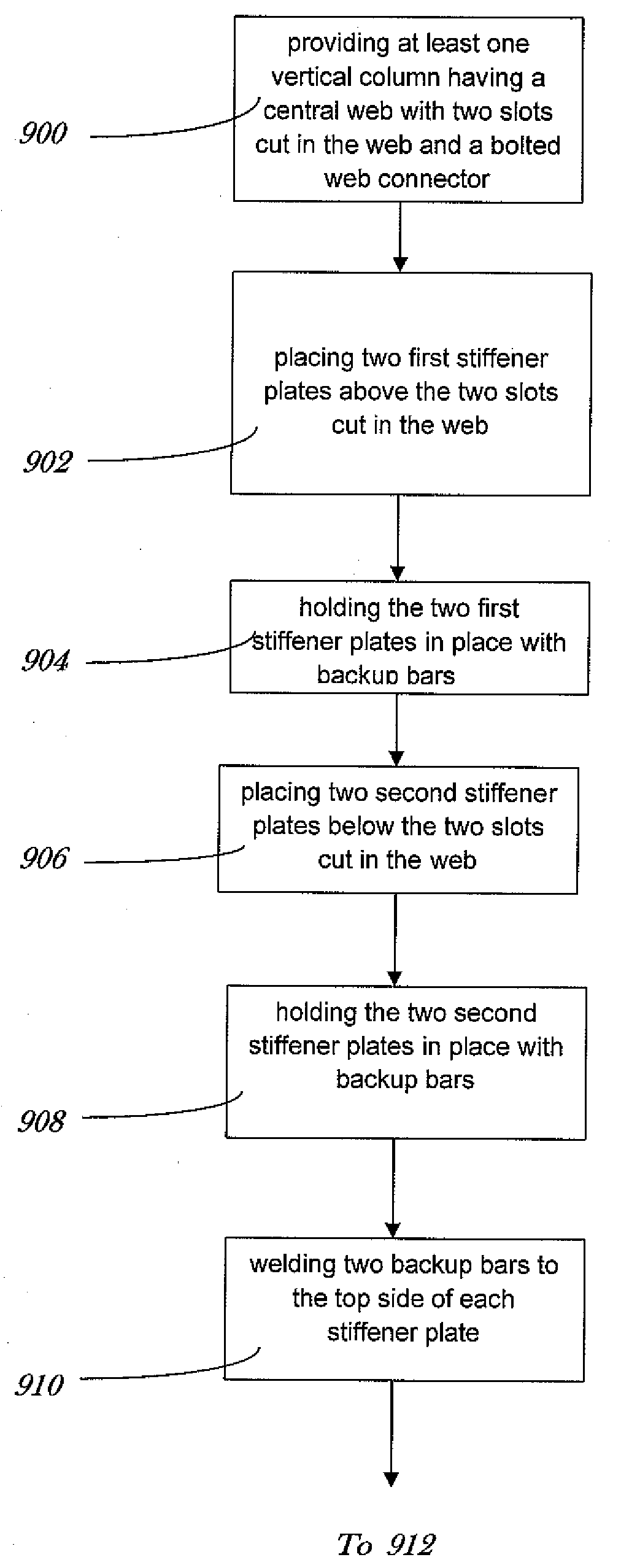
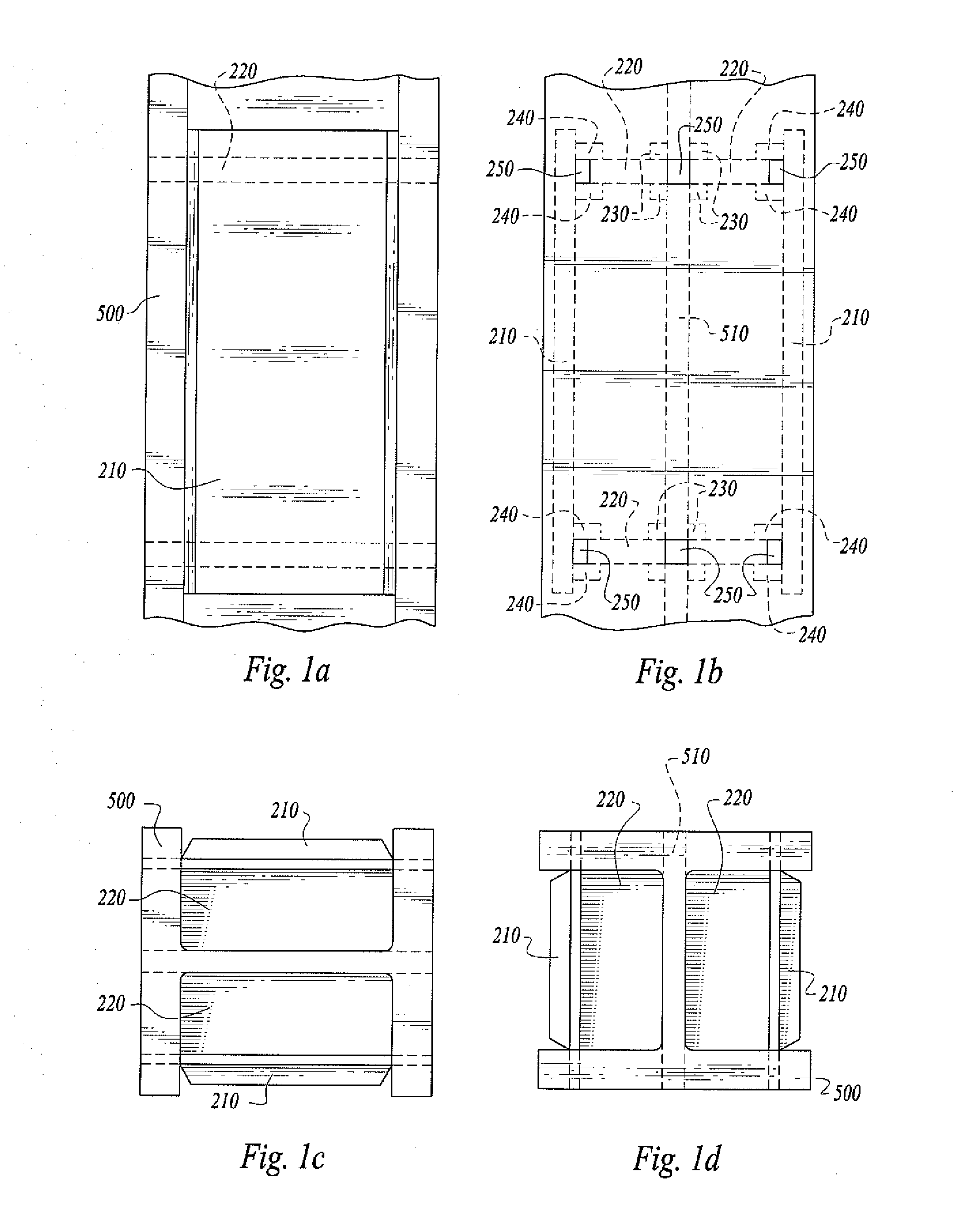
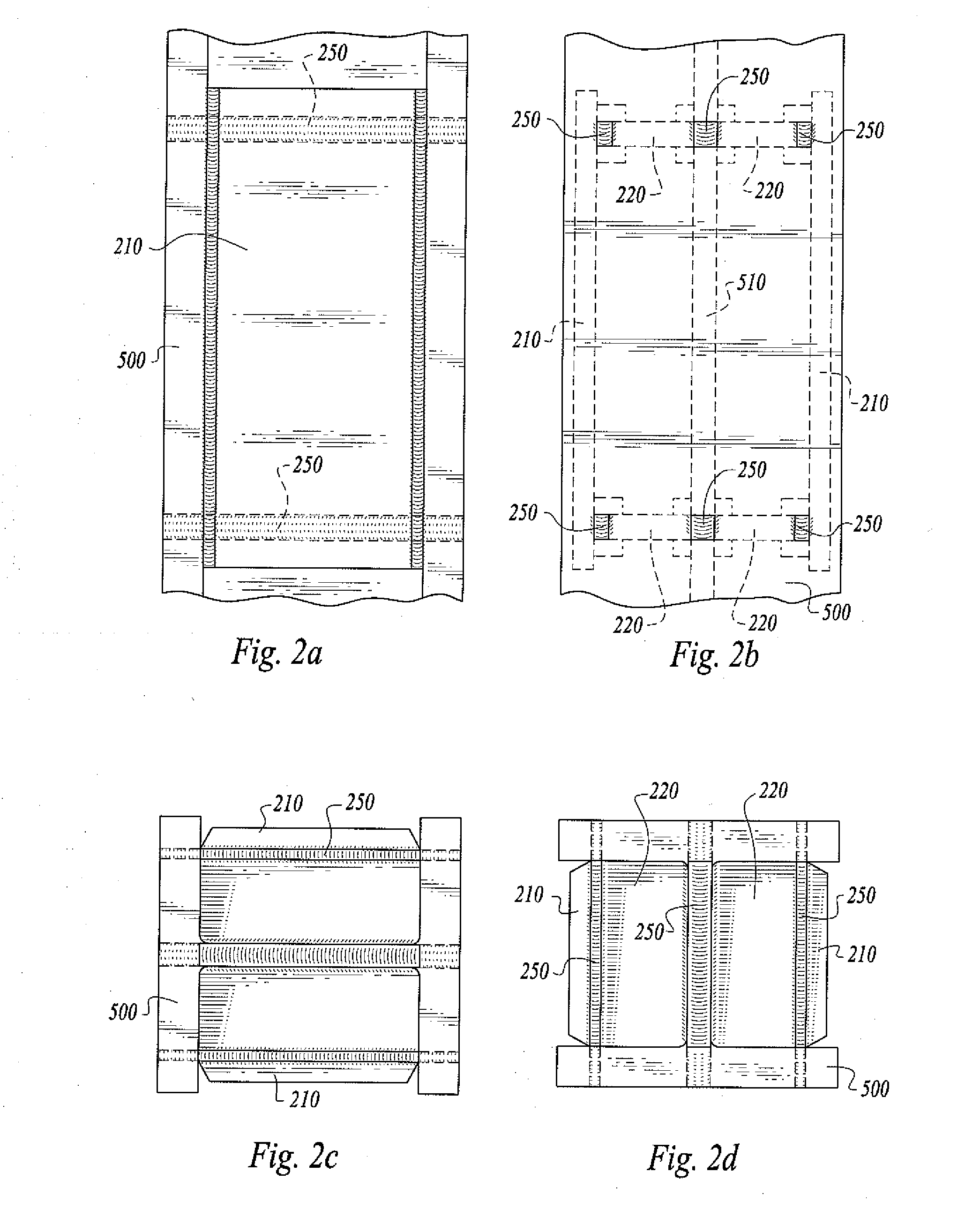
Either option presents a long and laborious process.

Method used


Image

  • System and method for vertical moment connection
  • System and method for vertical moment connection
  • System and method for vertical moment connection

Examples


Embodiment Construction

[0053]My following U.S. Letters Patent are incorporated by reference as if fully set forth herein: U.S. Pat. No. 6,297,472 for Welding System and Method, issued Oct. 2, 2001 (the “'472 Patent”); U.S. Pat. No. 7,038,159 for Electroslag Butt-Welding Expansion Joint Rails, issued May 2, 2006 (the “'159 Patent”); U.S. Pat. No. 7,148,443 for Consumable Guide Tube, issued Dec. 12, 2006 (the “'443 Patent”); U.S. Pat. No. 7,429,716 for Modular Welding System, issued Sep. 30, 2008 (the “'716 Patent”), and U.S. Pat. No. 7,550,692 [application Ser. No. 11 / 591,190], scheduled for issue on Jun. 23, 2009, for Consumable Guide Tube (the “'692 Patent”).

[0054]My following pending U.S. non-provisional patent applications are incorporated by reference as if fully set forth herein: U.S. application Ser. No. 11 / 591,190 for Consumable Guide Tube, filed Oct. 30, 2006 (the “'190 Application”); U.S. application Ser. No. 12 / 212,019 for System and Method of Electroslag Welding Spliced Vertical Columns, filed ...


PUM

PropertyMeasurementUnit
elliptical radiusaaaaaaaaaa
sizeaaaaaaaaaa
thicknessaaaaaaaaaa

Abstract

A system for narrow-gap electroslag-welded moment connections welded between vertical column flanges includes vertical column doubler plates with top and bottom stiffeners and horizontal beam side plates aligned with the doubler plates to carry the moment load through the vertical support columns. An embodiment includes an elliptical radius in each side plate. Disclosure of an automated modular method for narrow-gap electroslag-welded moment connections is included.

Description

CROSS-REFERENCES TO RELATED APPLICATIONS[0001]This United States non-provisional patent application is based upon and claims the filing date of U.S. provisional patent application Ser. No. 61 / 061,739 filed Jun. 16, 2008.STATEMENT REGARDING FEDERALLY SPONSORED RESEARCH OR DEVELOPMENT[0002]None.REFERENCE TO A MICRO-FICHE APPENDIX[0003]None.TECHNICAL FIELD[0004]This invention relates to welding. More particularly, the invention is related to a system and method for narrow-gap electroslag-welded moment connections (welded between the two vertical column flanges) for the construction of low-rise and high-rise buildings.BACKGROUND OF THE INVENTION[0005]My U.S. Pat. No. 6,297,472, issued Oct. 2, 2001, discloses and claims a welding system and method comprising a distributed welding control system that allows a welding operator to program automated welding cycles for various welding operations, that is particularly useful for installing stiffener plates onto structural beams. In U.S. Pat. N...

Claims


Application Information

Patent Timeline
Patent Type & Authority Applications(United States)
IPC IPC(8): B23K25/00
CPCB23K2201/28B23K25/00B23K2101/28
Inventor BONG, WILLIAM L.
Owner BONG WILLIAM L
Why Eureka
Try Eureka