
Foot Operated Lever-Lift Vertical Reel Unroller Assembly

a technology of lever-lifting and vertical reels, which is applied in the directions of transportation and packaging, thin material processing, filament handling, etc., can solve the problems of dangerous to workers lifting the reel, difficult positioning of the reel on the roller, and inability to roll into the oriented reel, etc., and achieves the effect of easy rotation

Inactive Publication Date: 2009-12-17
PRESS ROOM EQUIP LLC
View PDF5 Cites 5 Cited by
  • Summary
  • Abstract
  • Description
  • Claims
  • Application Information

AI Technical Summary

Benefits of technology

[0005]The lever lift assembly provides a device and process for lifting a reel onto raised rollers without the problems of the manual process described above. The lever lift assembly allows a single worker to roll the reel into position and raise the reel off the ground onto the rollers for easy rotation without assistance.
[0006]The lever lift assembly is safe, secure and positions the reel correctly on the rollers for dispensing the material from the reel, thus addressing the problems associated with the current method of raising loaded reels onto the rollers.

Problems solved by technology

Placing the reel on the rollers can be difficult given the size and weight of the reels, especially when loaded with material.
This is especially true since the vertically-oriented reel cannot be rolled into position on the rollers since they are raised above the floor.
Clearly this is dangerous to the workers lifting the reel and prone to accidents, lack of optimal positioning and other difficulties.

Method used


Image

  • Foot Operated Lever-Lift Vertical Reel Unroller Assembly
  • Foot Operated Lever-Lift Vertical Reel Unroller Assembly
  • Foot Operated Lever-Lift Vertical Reel Unroller Assembly

Examples


Embodiment Construction

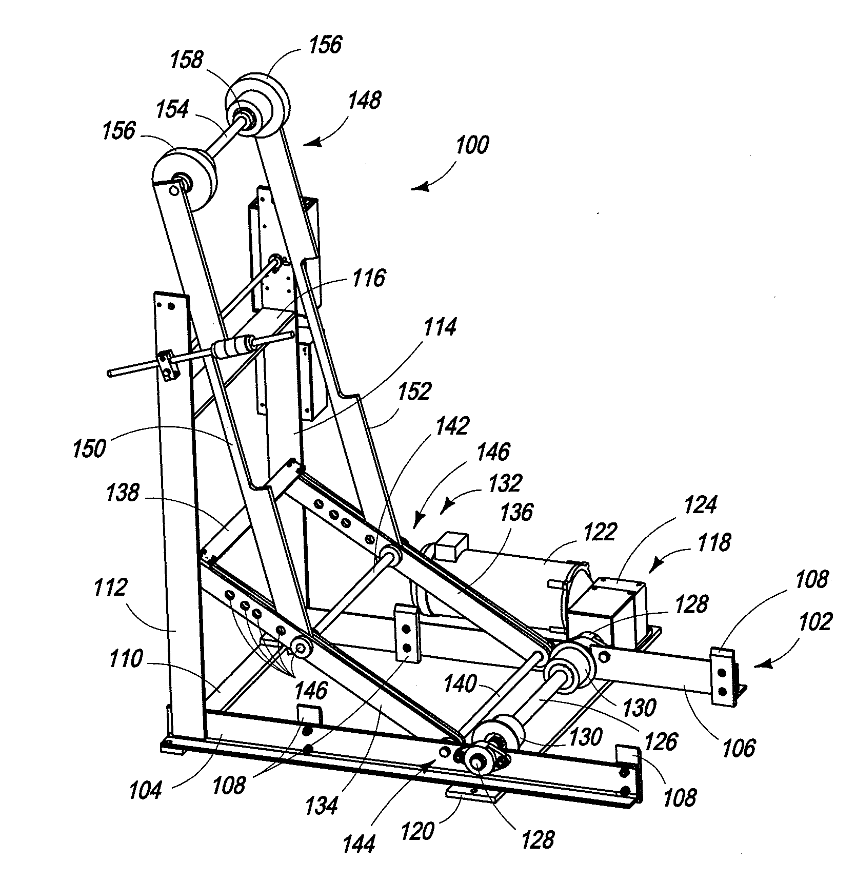
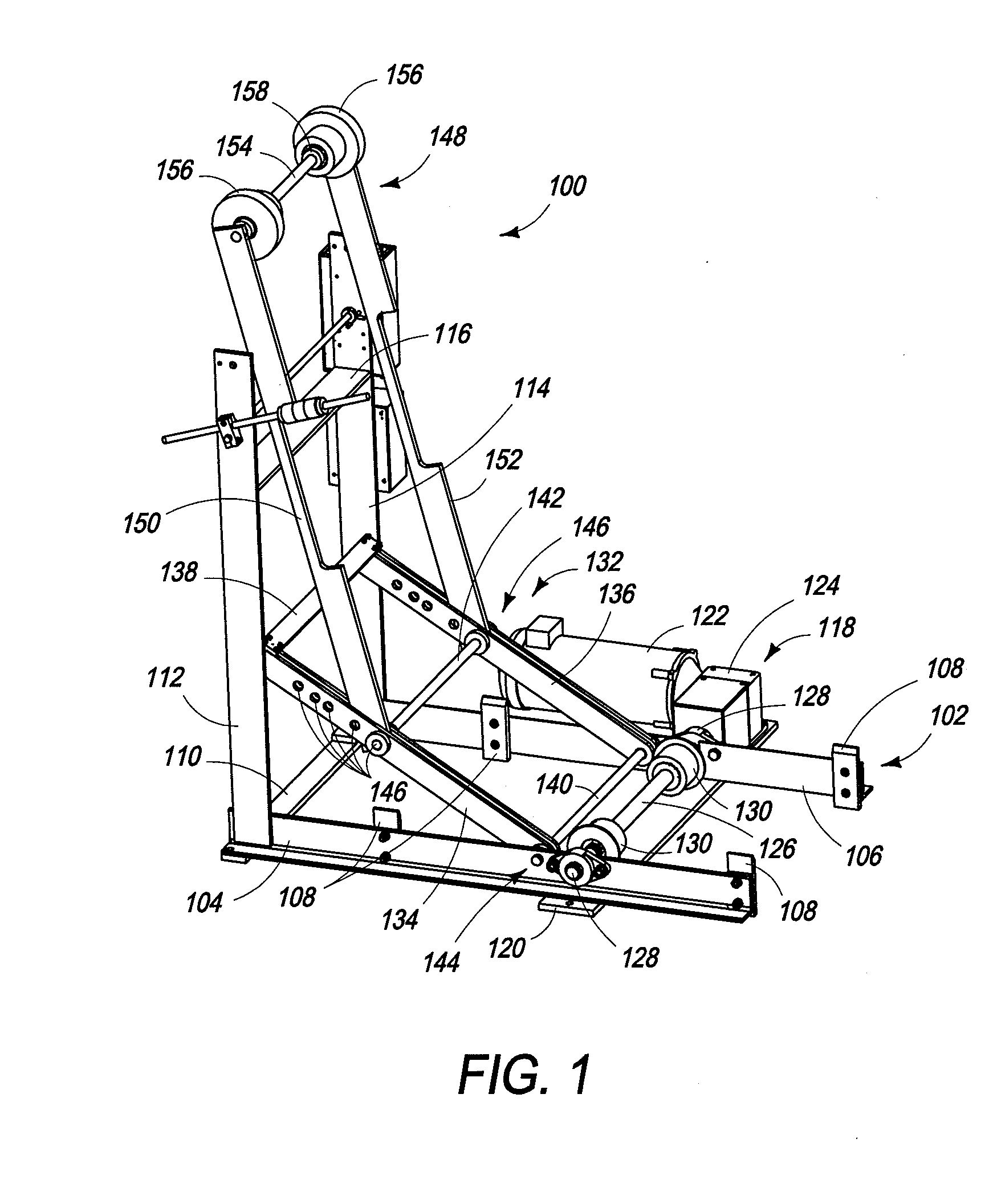
[0012]Referring now to FIG. 1, an embodiment of the lever lift assembly 100 is shown in a perspective view. The lever lift assembly includes a base assembly 102 to support the lever lift assembly 100 during use. A preferred embodiment of the lever lift assembly 100 comprises a first base member 104 and a second base member 106. In the embodiment shown in the figures, the first base member 104 and second base member 106 are formed from angle beams, specifically L beams, however the base members could also be formed from channel beams, box beams, I beams, or other structural members. Similarly, the base assembly 102 could be formed from a box or other structural component, or a sheet or plate of suitable material with appropriate mountings for the other components of the lever lift assembly 100, as described below.

[0013]In the embodiment shown in the figures, a plurality of guide flanges 108 are attached to the base assembly 102 at various points for guiding the other members of the l...


PUM


Abstract

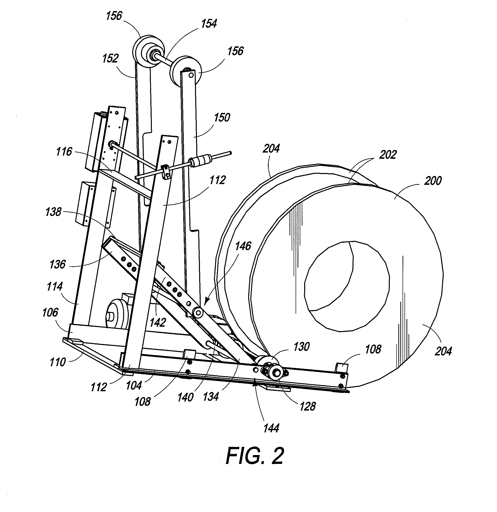
A lever lift assembly is provided for lifting a reel of cable, wire or other material off the floor. In one embodiment of the lever lift assembly, a lever assembly is actuated to retract a lifter assembly underneath the reel causing the reel to be lifted on a pair of drive wheels and a pair of flanged wheels. In one embodiment the lever lift assembly incorporates drive wheels to unroll material from the reel.

Description

BACKGROUNDField of the Invention[0001]Reels, or spools, of wire, cable and other material are widely used as an input to manufacturing and further processing of the cable and other materials. Reels provide a convenient method of storing the material, and, when in a vertical position, can be rolled as necessary to aid positioning of the reel on the flanged edges of the reel.[0002]Historically, reel platforms have been used to horizontally stack one or more spools of material. The platforms rotate as material is unspooled and may be powered to assist in spinning the spools. Spools are added to the platform using forklifts, hoists or other lifting mechanisms. More recently, vertical spool unreeling devices have come into use. When it is desired to remove material from the reel, the reel is often lifted and placed on raised rollers to allow the reel to rotate freely on the flanged edges of the reel, thus allowing the material on the reel to be unwound from the reel and processed as desi...

Claims


Application Information

Patent Timeline
Patent Type & Authority Applications(United States)
IPC IPC(8): B65H75/38
CPCB65H67/02B65H49/24
Inventor MALKIN, BRUCE
Owner PRESS ROOM EQUIP LLC
Learn More