

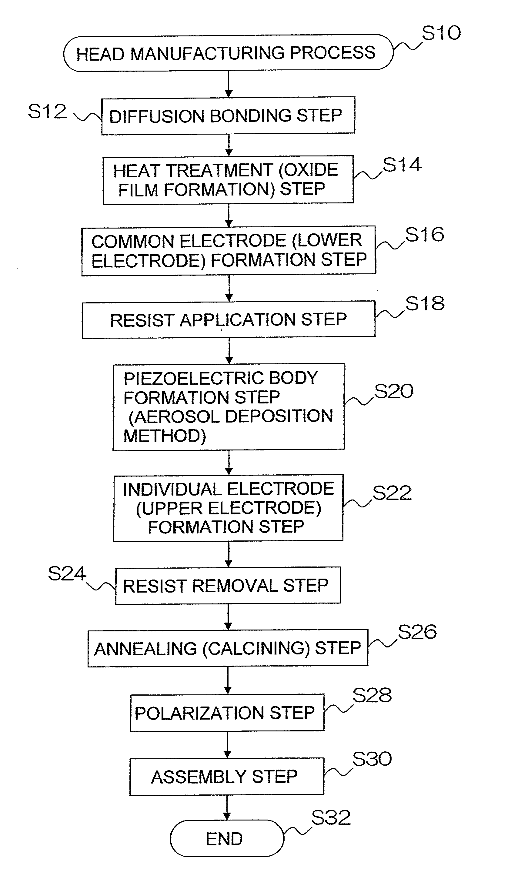
Method of manufacturing a piezoelectric actuator and liquid ejection head
a piezoelectric actuator and liquid ejection technology, applied in the direction of piezoelectric/electrostrictive transducers, generators/motors, inking apparatus, etc., can solve the problems of increasing the thickness of the diaphragm, reducing the displacement of the diaphragm, and increasing the manufacturing cost, so as to prevent the calcination of the piezoelectric body heat during the calcination process and prevent the deterioration of the pi
- Summary
- Abstract
- Description
- Claims
- Application Information
AI Technical Summary
Benefits of technology
Problems solved by technology
Method used
Image

Examples
Embodiment Construction
General Composition of Inkjet Recording Apparatus
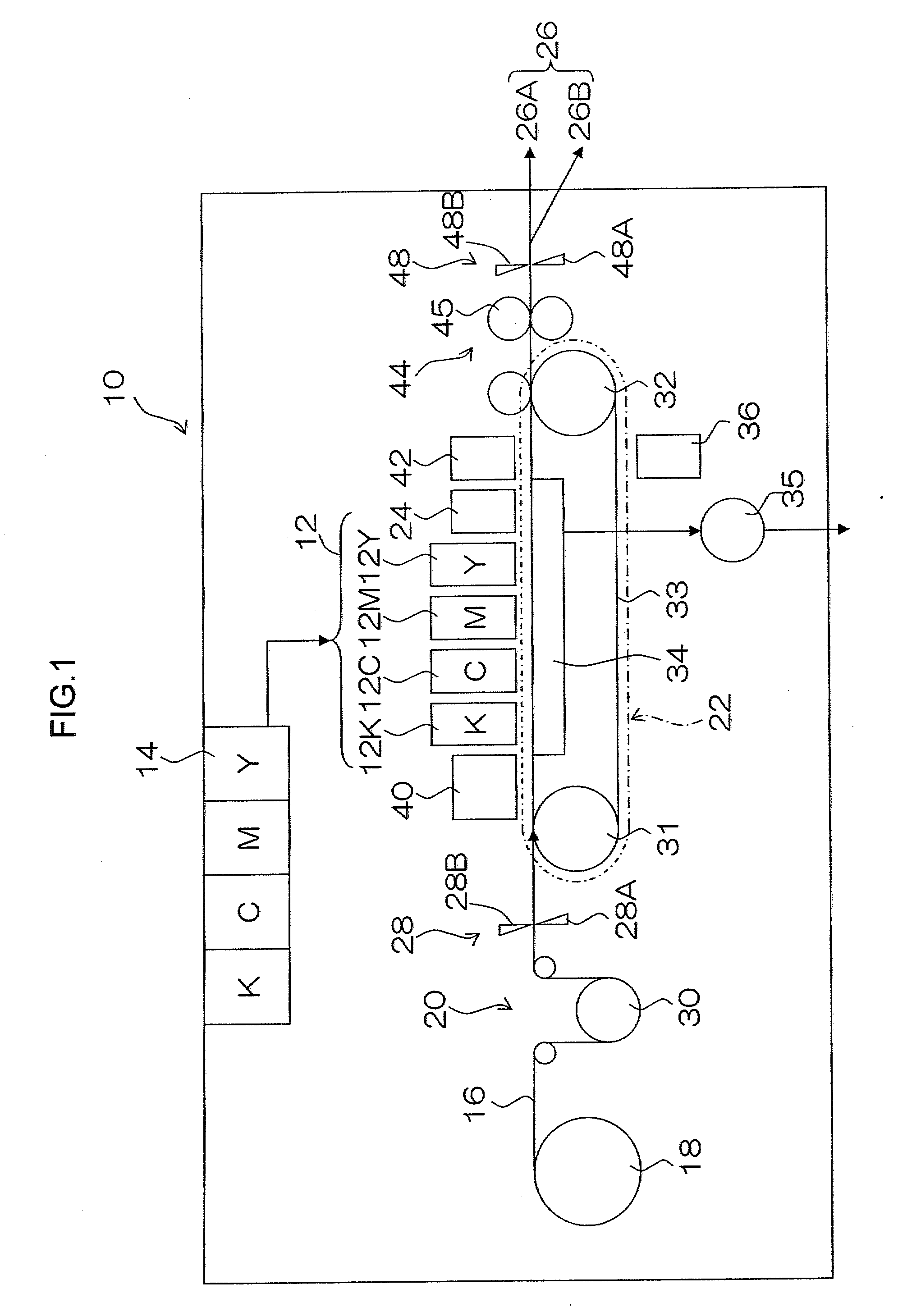
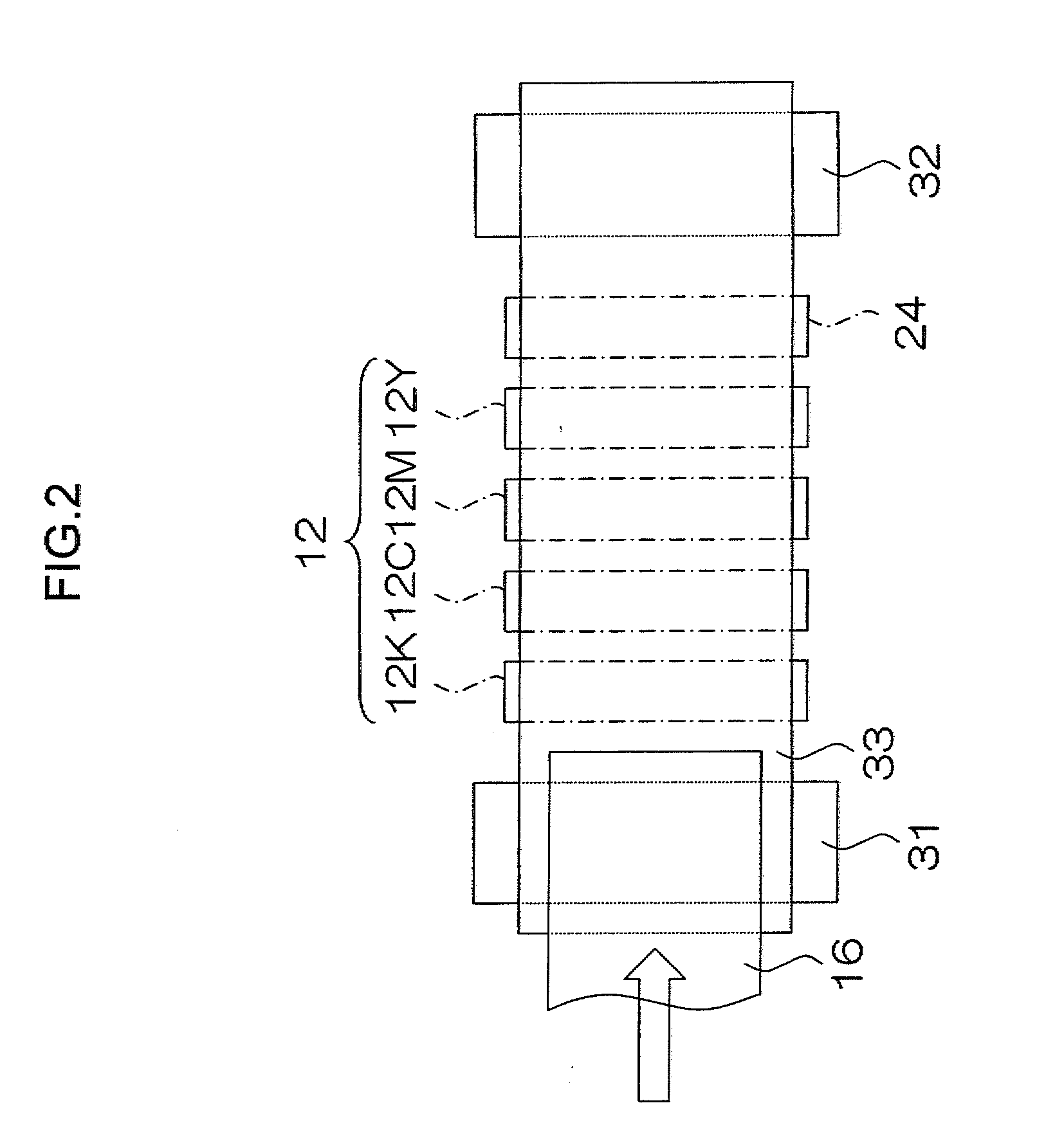
[0062]FIG. 1 is a general schematic drawing showing an embodiment of an inkjet recording apparatus according to an embodiment of the present invention. As shown in FIG. 1, the inkjet recording apparatus 10 comprises: a printing unit 12 having a plurality of heads 12K, 12C, 12M, and 12Y for ink colors of black (K), cyan (C), magenta (M), and yellow (Y), respectively; an ink storing and loading unit 14 for storing inks of K, C, M and Y to be supplied to the print heads 12K, 12C, 12M, and 12Y; a paper supply unit 18 for supplying recording paper 16; a decurling unit 20 for removing curl in the recording paper 16 supplied from the paper supply unit 18; a suction belt conveyance unit 22 disposed facing the nozzle faces (ink-droplet ejection faces) of the heads 12K, 12C, 12M, 12Y, for conveying the recording paper 16 (recording medium) while keeping the recording paper 16 flat; a print determination unit 24 for reading the printed result pr...
PUM
| Property | Measurement | Unit |
|---|---|---|
| temperature | aaaaa | aaaaa |
| temperature | aaaaa | aaaaa |
| temperature | aaaaa | aaaaa |
Abstract
Description
Claims
Application Information