
Super flat optical frequency com signal generator

Active Publication Date: 2009-12-17
NAT INST OF INFORMATION & COMM TECH
View PDF7 Cites 12 Cited by
  • Summary
  • Abstract
  • Description
  • Claims
  • Application Information

AI Technical Summary

Benefits of technology

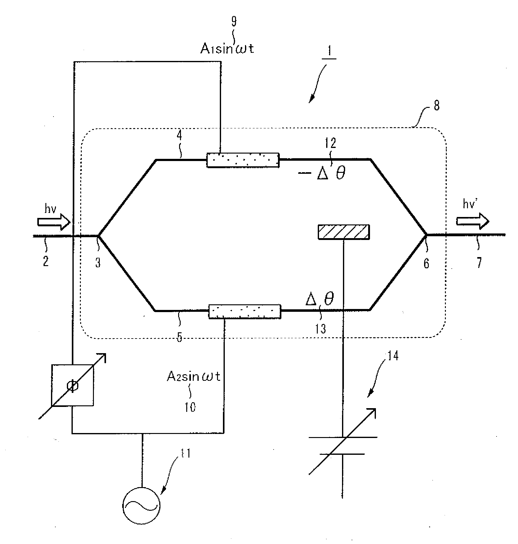
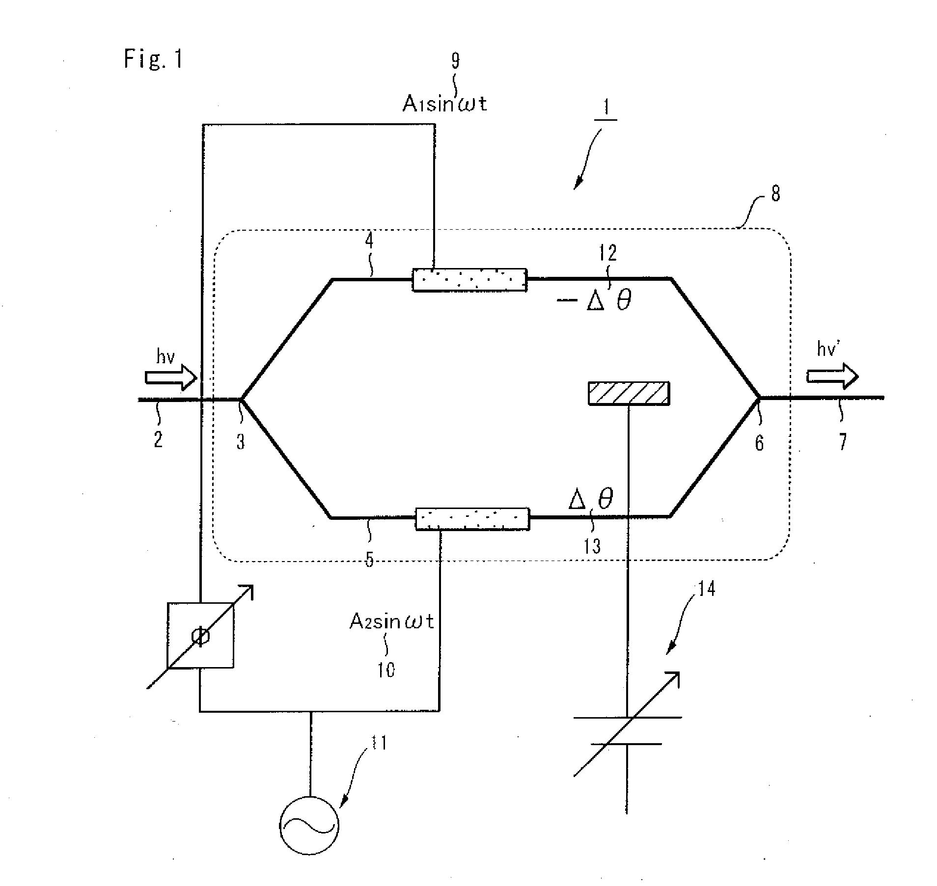
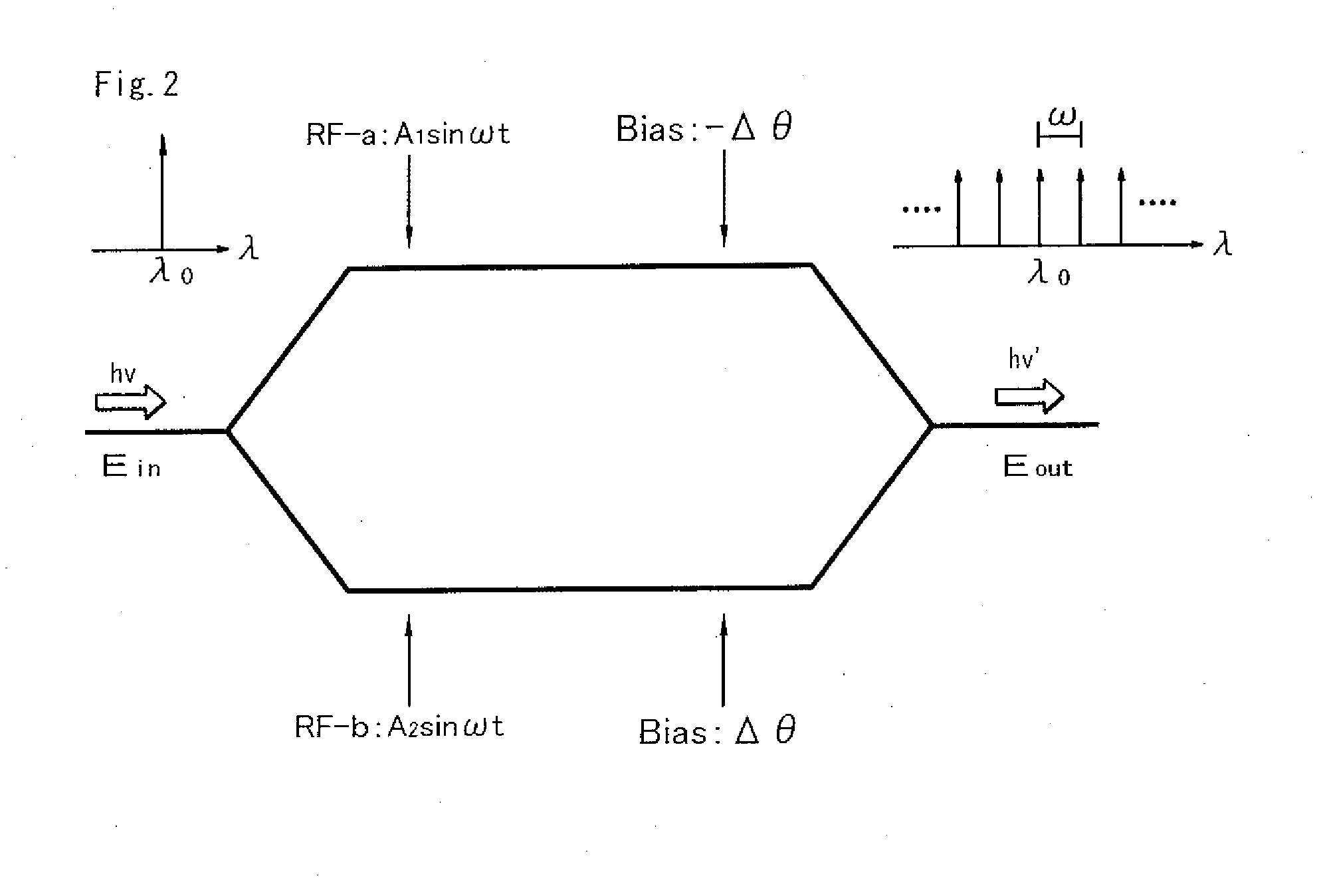
[0033]The present invention can provide an optical frequency comb signal generator, using single-stage optical modulator, which is capable of generating frequency comb signals with good spectral flatness, by means of droving the optical modulator in a predetermined condition. It makes system structure simple and easy to drive compared with a conventional optical frequency comb signal generator which has a phase modulators or two Mach-Zhender modulators because the apparatus of the present invention does not require driving two modulators using synchronized signals.
[0034]Because the optical pulse generator of the present invention has the above described optical frequency comb signal generator, the present invention can provide the optical pulse generator which has a meritorious effect as explained above.

Problems solved by technology

However, it is difficult to flatly generate an optical frequency comb using the EO modulation technique because the intensity of each mode is governed by Bessel functions and highly depends on wavelength.
However the conventional optical frequency comb signal generator has a drawback that it requires the synchronized driving for two optical modulators connected in tandem.
Thus the structure of the optical frequency comb signal generator become complex.

Method used


Image

  • Super flat optical frequency com signal generator
  • Super flat optical frequency com signal generator
  • Super flat optical frequency com signal generator

Examples


experiment 1

[Experiment 1]

[0104]FIG. 3 is a schematic diagram of the experimental setup to show that the optical frequency comb generator of the present invention can generate the comb signals with super spectrum flatness. In the FIG. 3, the same element numerals are indicated for the same element as in the FIG. 1. In the FIG. 3, the element numeral 15 indicates optical source, the numeral 16 indicates polarize controller, PC, and the numerals 17 and 18 indicate amplifiers, and the numeral 19 indicates spectrum analyzer. As shown in the FIG. 3, the optical frequency comb generator has DFB laser to generate CW light and an optical comb generation mechanism which comprises Mach-Zhender modulator. Further the optical comb generation mechanism comprises Mach-Zhender modulator which is used to modulate the optical signal outputted form CW light source, PC to control polarization of signal outputted from the CW light source, RF signal source, separator which separates output signals form the RF signa...


PUM


Abstract

An optical frequency COM generator generating an optical frequency COM having flat spectrum characteristics using a single modulator. The optical frequency COM generator has a drive signal system (11) and a bias signal system (14) which drive a first drive signal (9), a second drive signal (10) and bias signals (12, 13) to satisfy the following expression (I). ΔA+Δθ=π / 2 (I). (where, ΔA and Δθ are defined as ΔA≡(A1−A2) / 2 and Δθ≡(θ1−θ2) / 2, respectively, A1 and A2 represent the amplitudes of the first and second drive signals when they are inputted to the electrodes of the first and second drive signals, respectively, and θ1 and θ2represent the phases of bias voltages applied to first and second waveguides, respectively.)

Description

FIELD OF THE INVENTION[0001]The present invention relates generally to an optical frequency comb signal generator which generates super flat optical frequency comb signals using a Mach-Zhender modulator.[0002]More specifically, the present invention relates to an optical frequency comb signal generator which comprises a conventional Mach-Zehnder modulator capable of generating an optical frequency comb with excellent spectral flatness. The modulator is asymmetrically dual driven by large amplitude sinusoidal signals with different amplitudes. The driving condition to obtain spectral flatness is analytically derived and optimized, yielding a simple formula. This formula also predicts the conversion efficiency and bandwidth of the generated frequency comb.BACKGROUND OF ART[0003]Recently, many people study an optical frequency comb signal generator which can generate plurality of optical frequency components with same frequency intervals simultaneously. An optical frequency comb signal...

Claims


Application Information

Patent Timeline
IPC IPC(8): G02F1/225G02F1/01
CPCG02F1/2255G02F2203/56G02F2001/212G02F1/212
Inventor SAKAMOTO, TAKAHIDEKAWANISHI, TETSUYATSUCHIYA, MASAHIROIZUTSU, MASAYUKI
Owner NAT INST OF INFORMATION & COMM TECH
Features
  • Generate Ideas
  • Intellectual Property
  • Life Sciences
  • Materials
  • Tech Scout
  • Unparalleled Data Quality
  • Higher Quality Content
  • 60% Fewer Hallucinations
Learn More