Fuel cell stack

Inactive Publication Date: 2009-12-17
HONDA MOTOR CO LTD
View PDF5 Cites 17 Cited by
  • Summary
  • Abstract
  • Description
  • Claims
  • Application Information

AI Technical Summary

Benefits of technology

[0011]The present invention has been made to solve the problem of this type, and an object of the present invention is to provide a fue

Problems solved by technology

However, in the conventional technique, the spherical body 6 presses substantially the center of the surface pressure applying member 5 attached to the end of the fuel cell stack 3, and the swelling difference in the direction of gravity, in the electr

Method used


Image

  • Fuel cell stack
  • Fuel cell stack
  • Fuel cell stack

Examples


first embodiment

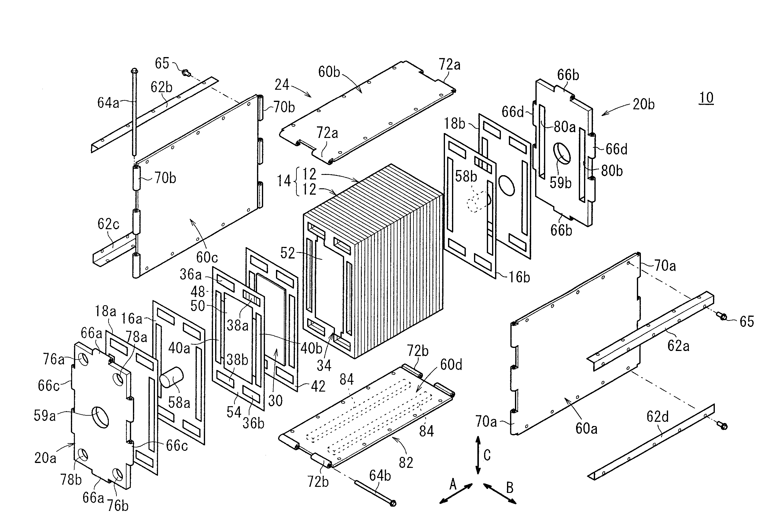
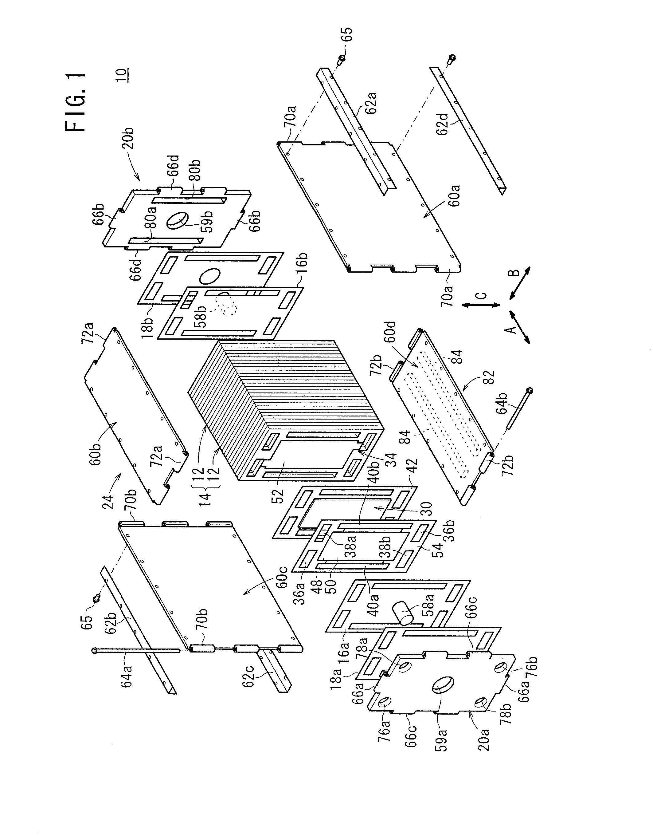
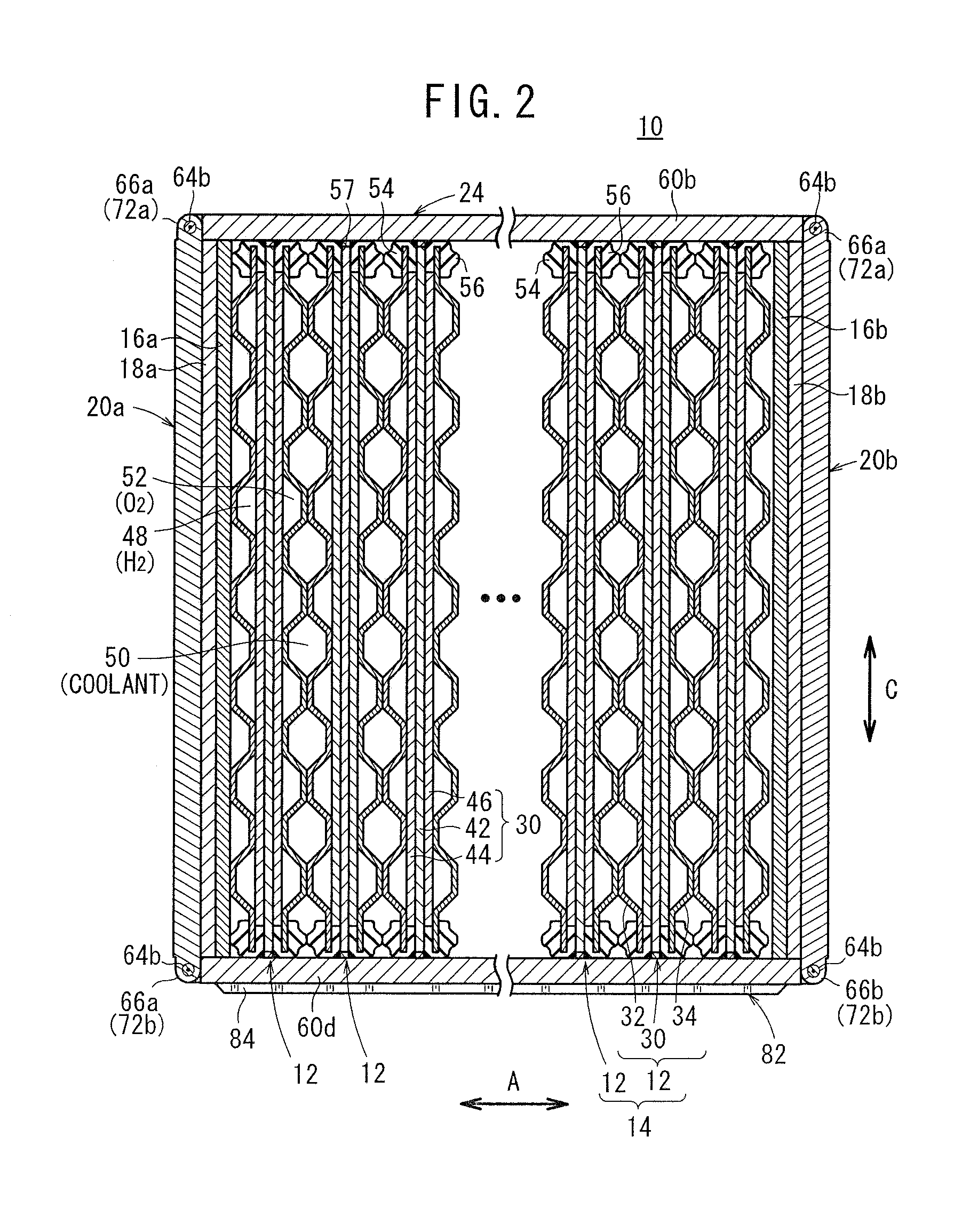
[0033]As shown in FIGS. 1 and 2, a fuel cell stack 10 according to the present invention includes a stack body 14 formed by stacking a plurality of unit cells 12 in a horizontal direction indicated by an arrow A. At one end of the stack body 14 in a stacking direction indicated by the arrow A, a terminal plate 16a is provided. An insulating plate 18a is provided outside the terminal plate 16a, and an end plate 20a is provided outside the insulating plate (insulator) 18a. At the other end of the stack body 14 in the stacking direction, a terminal plate 16b is provided. An insulating plate 18b (insulator) is provided outside the terminal plate 16b, and an end plate 20b is provided outside the insulating plate 18b. An insulating spacer member may be used as the insulating plate 18b. The fuel cell stack 10 is placed in a box-shaped casing 24 including the rectangular and vertically elongate end plates 20a, 20b.

[0034]As shown in FIGS. 2 and 3, each of the unit cells 12 is formed by sand...

third embodiment

[0071]FIG. 6 is a partial cross sectional view showing a fuel cell stack 100 according to the present invention.

[0072]In the fuel cell stack 100, each of the unit cells 12 has stack deformation prevention structure 102. The stack deformation prevention structure 102 is configured such that elastic modulus of ends 54a, 56a on the upper side of the first and second seal members 54, 56 in the direction of gravity is higher than elastic modulus of ends 54b, 56b on the lower side of the first and second seal members 54, 56 in the direction of gravity. Specifically, cross sectional areas of the first and second seal members 54, 56 or materials of the first and second seal members 54, 56 are changed for changing the elastic modulus.

[0073]In the third embodiment, elastic modulus of the ends 54a, 56a on the upper side of the first and second seal members 54, 56 in the direction of gravity is higher than elastic modulus of the ends 54b, 56b on the lower side of the first and second seal membe...

fourth embodiment

[0075]FIG. 7 is a side view showing a unit cell 12 of a fuel cell stack 110 according to the present invention.

[0076]In the fuel cell stack 110, each of the unit cells 12 has stack deformation prevention structure 112. The stack deformation prevention structure 112 is configured such that the thickness (t1) on the lower side of the first and second metal separators 32, 34 in the direction of gravity is smaller than the thickness (t2) on the upper side of the first and second metal separators 32, 34 in the direction of gravity (t12).

[0077]In the fourth embodiment, in each of unit cells 12, deformation in the stacking direction occurs easily on the lower side in the direction of gravity, in comparison with the upper side in the direction of gravity. It is because the thickness (t1) on the lower side of the first and second metal separators 32, 34 is smaller than the thickness (t2) on the upper side of the first and second metal separators 32, 34. Therefore, when the lower side of the ...


PUM


Abstract

A casing of a fuel cell stack has stack deformation prevention structure for limiting the change of an interval between end plates on the lower side in a direction of gravity, due to swelling of the lower side of the stack body in the direction of gravity. The stack deformation prevention structure is configured such that elastic modulus of a side plate provided on a lower side of the stack body in the direction of gravity is higher than elastic modulus of a side plate provided on an upper side of the stack body in the direction of gravity.

Description

BACKGROUND OF THE INVENTION[0001]1. Field of the Invention[0002]The present invention relates to a fuel cell stack which includes a stack body formed by stacking a plurality of unit cells in a horizontal direction, and a pair of end plates sandwiching the stack body. Each of the unit cells includes an electrolyte electrode assembly and separators sandwiching the electrolyte electrode assembly. The electrolyte electrode assembly includes a pair of electrodes and an electrolyte interposed between the electrodes.[0003]2. Description of the Related Art[0004]For example, a solid polymer electrolyte fuel cell employs an electrolyte membrane (electrolyte) comprising a polymer ion exchange membrane. The electrolyte membrane is interposed between an anode and a cathode to form a membrane electrode assembly. The membrane electrode assembly is sandwiched between separators to form a fuel cell. In use, normally, a predetermined number of (e.g., several tens to several hundreds of) fuel cells ar...

Claims


Application Information

Patent Timeline
IPC IPC(8): H01M8/10
CPCH01M8/1002H01M8/241Y02E60/521H01M8/2475H01M8/248H01M8/247H01M8/1007Y02E60/50H01M8/2483H01M8/242H01M8/0267H01M8/0258
Inventor TAKAHASHI, KENWACHI, DAISUKE
Owner HONDA MOTOR CO LTD
Why Eureka
Try Eureka