Travel Assembly for Dump Truck

a technology for travel parts and dump trucks, which is applied in mechanical equipment, gearing details, transportation and packaging, etc., can solve the problems of deterioration in lubrication performance, malfunction or seizure of the reduction gear unit, and deterioration of lubrication performance, so as to facilitate the effective recovery of lube oil, reduce the amount of lube oil, and reduce the height of the level of lube oil

Active Publication Date: 2009-12-17
NIHON KENKI CO LTD
View PDF6 Cites 12 Cited by
  • Summary
  • Abstract
  • Description
  • Claims
  • Application Information

AI Technical Summary

Benefits of technology

[0016]Further, the cooled lube oil is supplied to the reduction gear unit. It is, therefore, unnecessary to rely upon the amount of lube oil to compensate for a deterioration in the lubrication performance of lube oil. This has made it possible to lower the height of the level of lube oil relative to the reduction gear unit, in other words, to reduce the amount of lube oil to be used for the lubrication of the reduction gear unit.
[0017]Preferably, the suction pipe in the recovery oil passage may be open on a side of an outer periphery of the spindle at a location radially outer than the two bearings, and the communication holes are formed through the wheel. This preferred embodiment can facilitate the effective recovery of lube oil even when the height of oil level becomes lower under centrifugal force and inertia force.
[0018]Moreover, the suction pipe extends through the oil inlet hole, in other words, the oil inlet hole also serves as a hole, through which the suction pipe extends, in addition to its primary function. The present invention, therefore, can contribute to a reduction in the machining man-hour for the arrangement of the recovery oil passage.
[0019]As mentioned above, the present invention circulates lube oil for the reduction gear unit between the reduction gear unit and the oil cooler through the cooling circuit so that the lube oil can be cooled during travel of the dump truck. The present invention can, therefore, contribute to the prevention of malfunction or seizure of the reduction gear unit.

Problems solved by technology

This overheating deteriorates the lubrication performance of the lube oil.
This deterioration in lubrication performance may become a cause of malfunction or seizure of the reduction gear unit.

Method used


Image

  • Travel Assembly for Dump Truck
  • Travel Assembly for Dump Truck
  • Travel Assembly for Dump Truck

Examples


Embodiment Construction

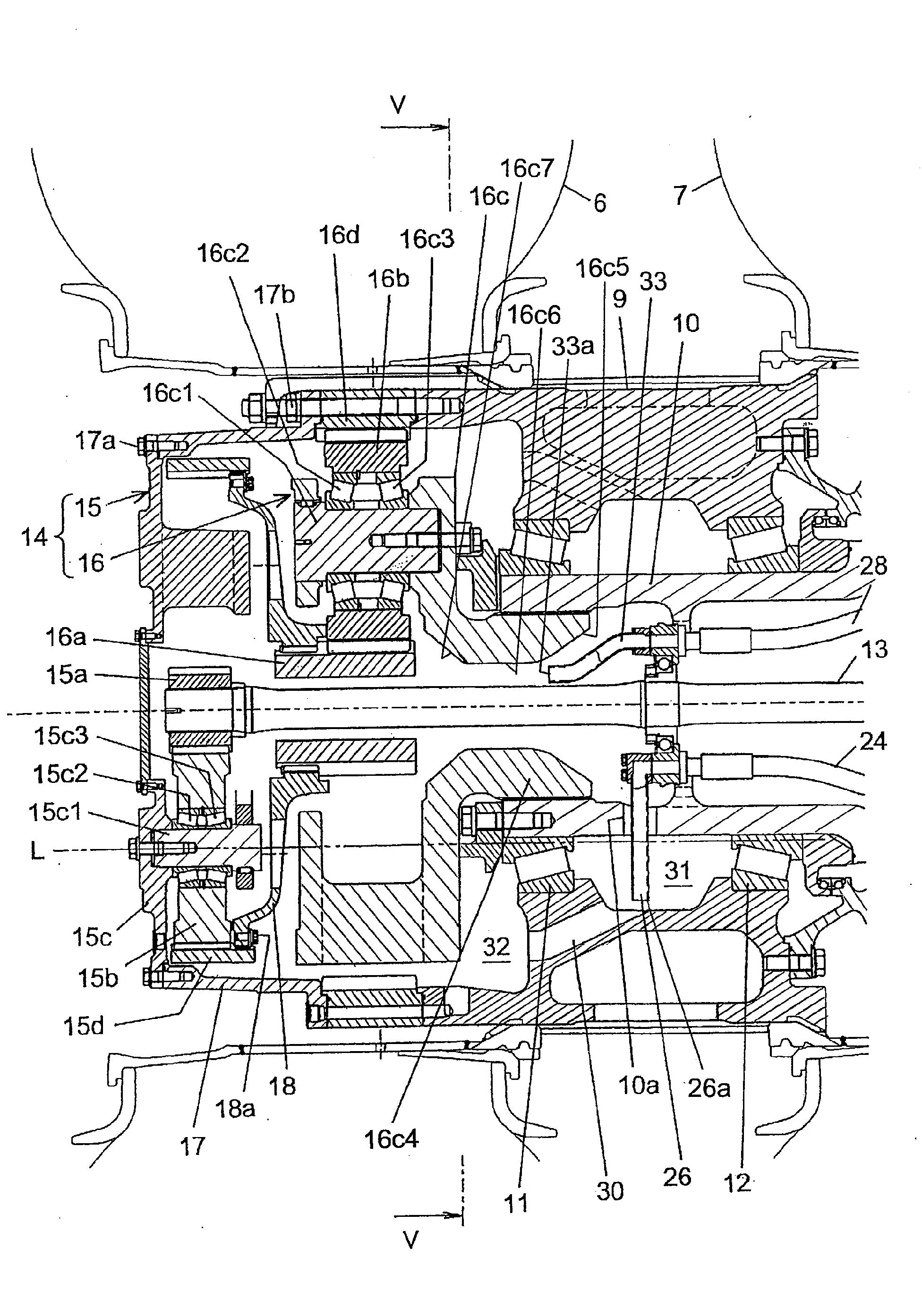
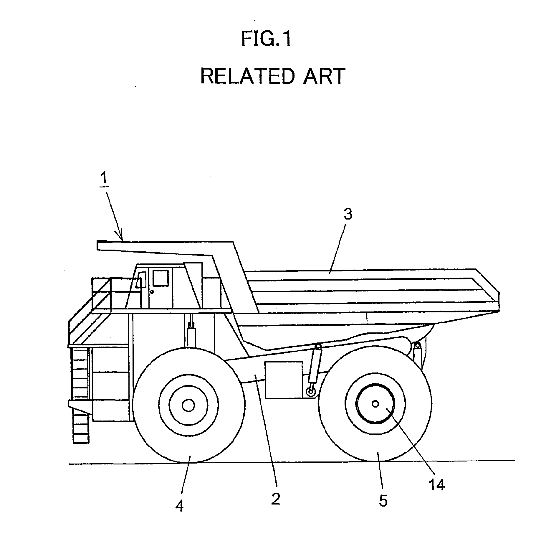
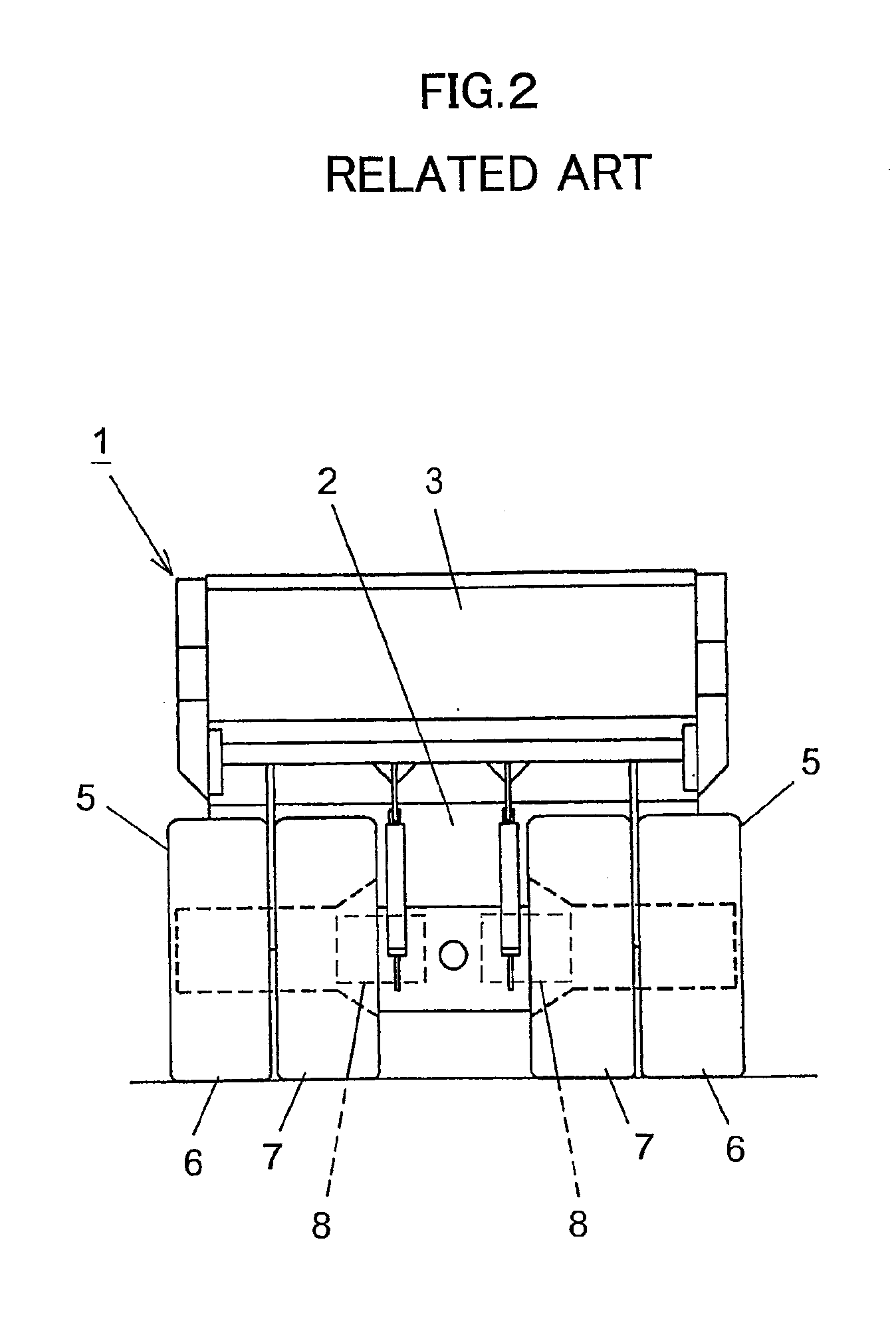
[0026]With reference to FIGS. 4 through 6, a description will hereinafter be made about a travel assembly according to one embodiment of the present invention for a dump truck. Similar to the above-described conventional travel assembly for the dump truck, the travel assembly according to the one embodiment of the present invention can also be arranged on the dump truck 1 shown in FIGS. 1 and 2.

[0027]Among the elements of structure depicted in FIG. 4, like elements to those illustrated in FIG. 3 are designated by like reference numerals, and such like elements will also be described again below.

[0028]As depicted in FIG. 4, the travel assembly according to this embodiment has, like the conventional travel assembly, the wheel 9 on which the tires 6, 7 are to be mounted as double tires, the spindle 10 non-rotatably fixed on the chassis 2 (see FIG. 2) in the state that the spindle 10 is inserted on the side of the inner periphery of the wheel 9, and the two bearings 11, 12 arranged side...


PUM


Abstract

Wheels of a dump truck are each provided with a travel assembly for transmitting an output of an electric motor to the wheel via a reduction gear unit. The travel assembly is provided with a cooling circuit for cooling lube oil. The cooling circuit has an oil cooler and a recovery oil passage for guiding lube oil from a side of the gear unit to the cooler. The recovery oil passage has an intra-spindle recovery line inserted on a side of an inner periphery of a spindle, a suction pipe extending from the recovery line to a space surrounded by the spindle, the wheel and two spindle-supporting bearings, and communication holes formed in the wheel to communicate the side of the reduction gear unit with the space.

Description

CROSS-REFERENCE TO RELATED APPLICATION[0001]This application claims the priority of Japanese Patent Application 2008-154276 filed Jun. 12, 2008, which is incorporated herein by reference.BACKGROUND OF THE INVENTION[0002]1. Field of the Invention[0003]This invention relates to a travel assembly for a dump truck, which serves to transmit an output of its corresponding electric motor to an associated wheel by way of a reduction gear unit such that the dump truck is allowed to travel.[0004]2. Description of the Related Art[0005]As travel assemblies for dump trucks, there are those which transmit an output of a diesel engine to a tire wheel by using a differential and those which drive an electric motor with electric power generated by a diesel engine and transmit an output of the electric motor to a tire wheel by a reduction gear unit including a planetary gear mechanism. Dump trucks include large ones having payload capacity of greater than 100 tons and employed in mines. As travel ass...

Claims


Application Information

Patent Timeline
Patent Type & Authority Applications(United States)
IPC IPC(8): F16H57/04F16H57/02
CPCB60K7/0007B60K17/046B60K2007/0038F16H57/0486F16H57/0412F16H57/0423B60K2007/0092
Inventor SHIBUKAWA, TAKESHIMASUDA, HAYATO
Owner NIHON KENKI CO LTD
Why Eureka
Try Eureka