Wearing article and method of manufacturing the same

a technology of wearing articles and manufacturing methods, applied in the field of wearing articles, can solve the problems of increasing the cost of facilities and occurrence of material loss, and achieve the effect of satisfying wearing comfort and enhancing appearan

Active Publication Date: 2009-12-17
ZUIKO CORP
View PDF19 Cites 32 Cited by
  • Summary
  • Abstract
  • Description
  • Claims
  • Application Information

AI Technical Summary

Benefits of technology

[0011]Hence, according to the invention, not only is it possible to reduce a loss of materials in comparison with a conventional wearing article that causes a loss of materials in an amount comparable to the opening areas of the leg openings, but it is also possible to reduce the cost of facilities because the facility needed for the work to cut out the leg openings can be omitted.
[0012]Further, according to the invention, the fastening occurs in the crotch portion by the shirring (corrugated shape formed by gathering a sheet material in folds, such as gathers, pleats, and creases) formed in the crotch portion. The crotch portion is therefore pulled upward (in a direction toward the waist opening from the leg openings) and forms a gusset when put on the wearer, and the wearing article takes on the shape of a trunks type. It is thus possible to achieve satisfactory wearing comfort and enhance the appearance when put on the wearer.
[0016]Hence, according to the manufacturing method of a wearing article of the invention, not only is it possible to reduce a loss of materials in comparison with a conventional wearing article that causes a loss of materials in an amount comparable to the opening areas of the leg openings, but it is also possible to reduce the cost of facilities because the facility needed for the work to cut out the leg openings can be omitted.
[0017]Further, according to the invention, because the shirring is formed in the crotch outer sheet along the direction crossing the flowing direction, the fastening occurs in the crotch portion in the completed wearing article by the shirring formed in the crotch portion (crotch outer web). The crotch portion is therefore pulled upward and forms a gusset when put on the wearer, and the wearing article takes on the shape of a trunks type. It is thus possible to achieve satisfactory wearing comfort and enhance the appearance when put on the wearer.
[0022]Hence, according to the manufacturing method of a wearing article of the invention, not only is it possible to reduce a loss of materials in comparison with a conventional wearing article that causes a loss of materials in an amount comparable to the opening areas of the leg openings, but it is also possible to reduce the cost of facilities because the facility needed for the work to cut out the leg openings can be omitted.
[0023]Further, according to the invention, because the first crotch elastic member in a stretched state can be attached to a region that will be made into the crotch portion when the wearing article is completed, fastening occurs in the crotch portion in the completed wearing article due to a shrinkage force of the first crotch elastic member. The crotch portion is therefore pulled upward and forms a gusset when put on the wearer, and the wearing article takes on the shape of a trunks type. It is thus possible to achieve satisfactory wearing comfort and enhance the appearance when put on the wearer.

Problems solved by technology

However, because leg openings are made in the web, the manufacturing method of Patent document 1 has problems that not only pieces cut away from the web to be thrown away result in the occurrence of a loss of materials, but also the need for a special apparatus for cutting out the web increases the cost of facilities.

Method used


Image

  • Wearing article and method of manufacturing the same
  • Wearing article and method of manufacturing the same
  • Wearing article and method of manufacturing the same

Examples


Embodiment Construction

[0034]Hereinafter, preferred embodiments of the invention will be described with reference to the drawings.

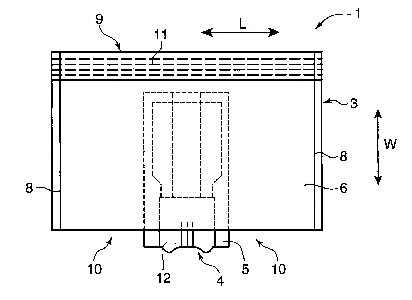
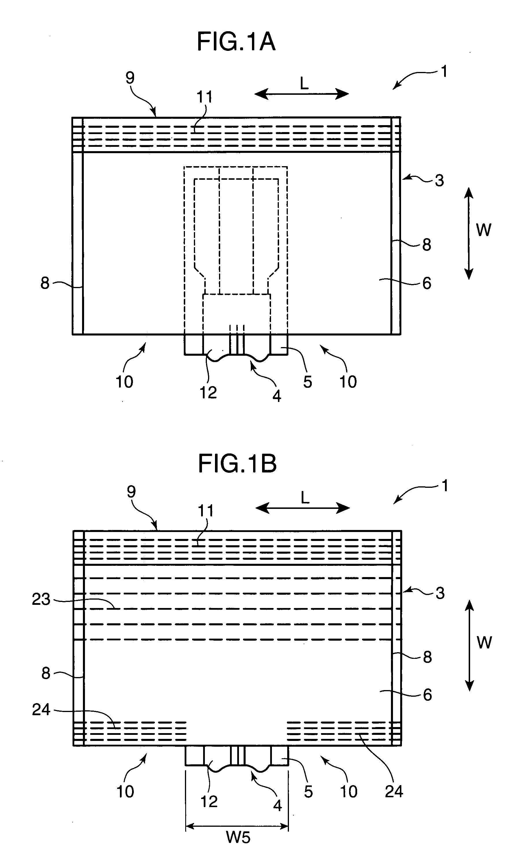
[0035]FIG. 1A is a plan view showing trunks-type disposable pants 1 as an example of a wearing article of the invention, and FIG. 1B is a plan view showing trunks-type disposable pants 2 according to another embodiment.

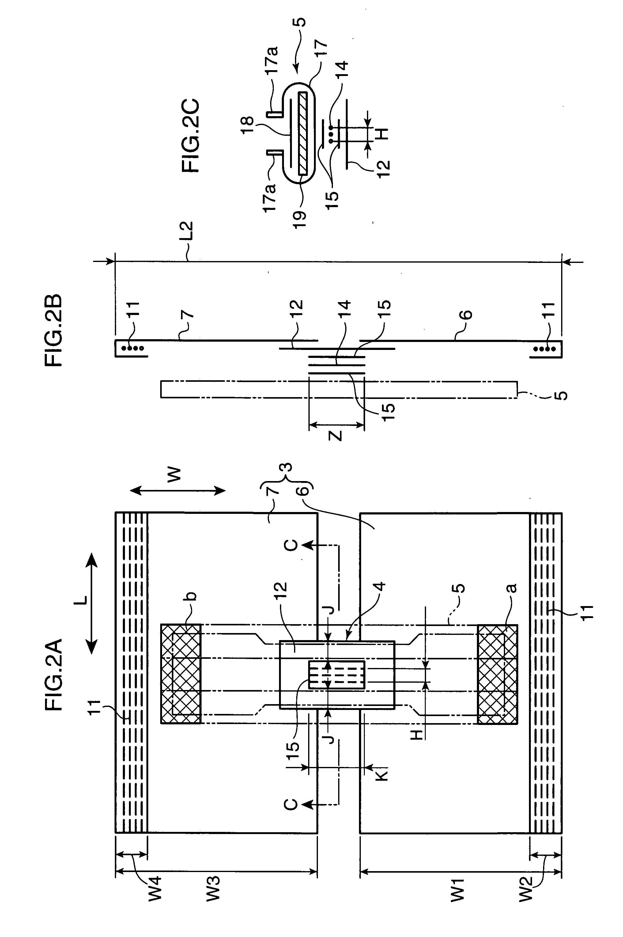
[0036]FIG. 2 is a development view of the disposable pants 1 of FIG. 1A. FIG. 2A is a plan view, FIG. 2B is a side view of FIG. 2A, and FIG. 2C is a cross section taken on line C-C of FIG. 2A. An absorber 5 described below is indicated by a solid line in FIG. 2C and indicated by a virtual line in FIGS. 2A and 2B for ease of illustration.

[0037]FIG. 3 is an exploded perspective view of the disposable pants 1 of FIG. 1.

[0038]Referring to the respective drawings, the disposable pants 1 include a waist portion 3 that continuously surrounds the waist of the wearer, a crotch portion 4 running under the crotch of the wearer, and the absorber 5 provided to cover the inner...


PUM

PropertyMeasurementUnit
distanceaaaaaaaaaa
shapeaaaaaaaaaa
shrinkage forceaaaaaaaaaa

Abstract

A wearing article capable of suppressing the occurrence of a loss of materials and an increase of the cost of facilities and a method of manufacturing the same are provided. A wearing article includes a waist portion (3) formed in a ring shape capable of continuously surrounding the waist of the wearer and using one of openings as a waist opening (9), and a crotch portion (4) joined to the waist portion (3) across an opening on the opposite side to the waist opening (9) so that the crotch portion (4) and the waist portion (3) define a pair of leg openings (10) for the wearer to put through his legs individually. Shirring is formed in the crotch portion (4) so as to shorten the distance between the mutually opposing inner surfaces of the waist portion (3) connected to each other by the crotch portion (4).

Description

BACKGROUND OF THE INVENTION[0001]1. Field of the Invention[0002]The present invention relates to a wearing article and a method of manufacturing the same.[0003]2. Description of the Related Art[0004]For instance, boxer shorts known as the wearing article are manufactured by the manufacturing method disclosed in Patent Document 1.[0005]The manufacturing method of Patent Document 1 adopts the step of transporting a strip-shaped web along the longitudinal direction thereof while making leg openings penetrating through the web in the thickness direction, and then folding the web in the width direction.[0006]However, because leg openings are made in the web, the manufacturing method of Patent document 1 has problems that not only pieces cut away from the web to be thrown away result in the occurrence of a loss of materials, but also the need for a special apparatus for cutting out the web increases the cost of facilities.[0007]The invention was devised in view of the problems discussed a...

Claims


Application Information

Patent Timeline
Patent Type & Authority Applications(United States)
IPC IPC(8): A61F13/45B32B37/00B32B38/04
CPCA41B9/001A61F13/15699A61F13/15723Y10T156/1052A61F2013/49063Y10T156/1084A61F13/496
Inventor UMEBAYAHI, TOYOSHIKURATA, SHUHEI
Owner ZUIKO CORP
Why Eureka
Try Eureka