
Steerable and flexibly curved probes

a probe and flexural technology, applied in the field of insertable probes, can solve the problems of reducing the effectiveness of prior art laser probes, unable to use probes with great difficulty, and reducing the intensity of laser probes, so as to achieve the effect of better access to interior areas

Active Publication Date: 2009-12-17
SPAIDE RICHARD F
View PDF4 Cites 113 Cited by
  • Summary
  • Abstract
  • Description
  • Claims
  • Application Information

AI Technical Summary

Benefits of technology

The steerable probe can reach previously inaccessible areas of the eye, maintain maximum laser intensity by directing the beam perpendicularly to the coagulation site, and reduce trauma to intraocular structures with its flexible design.

Problems solved by technology

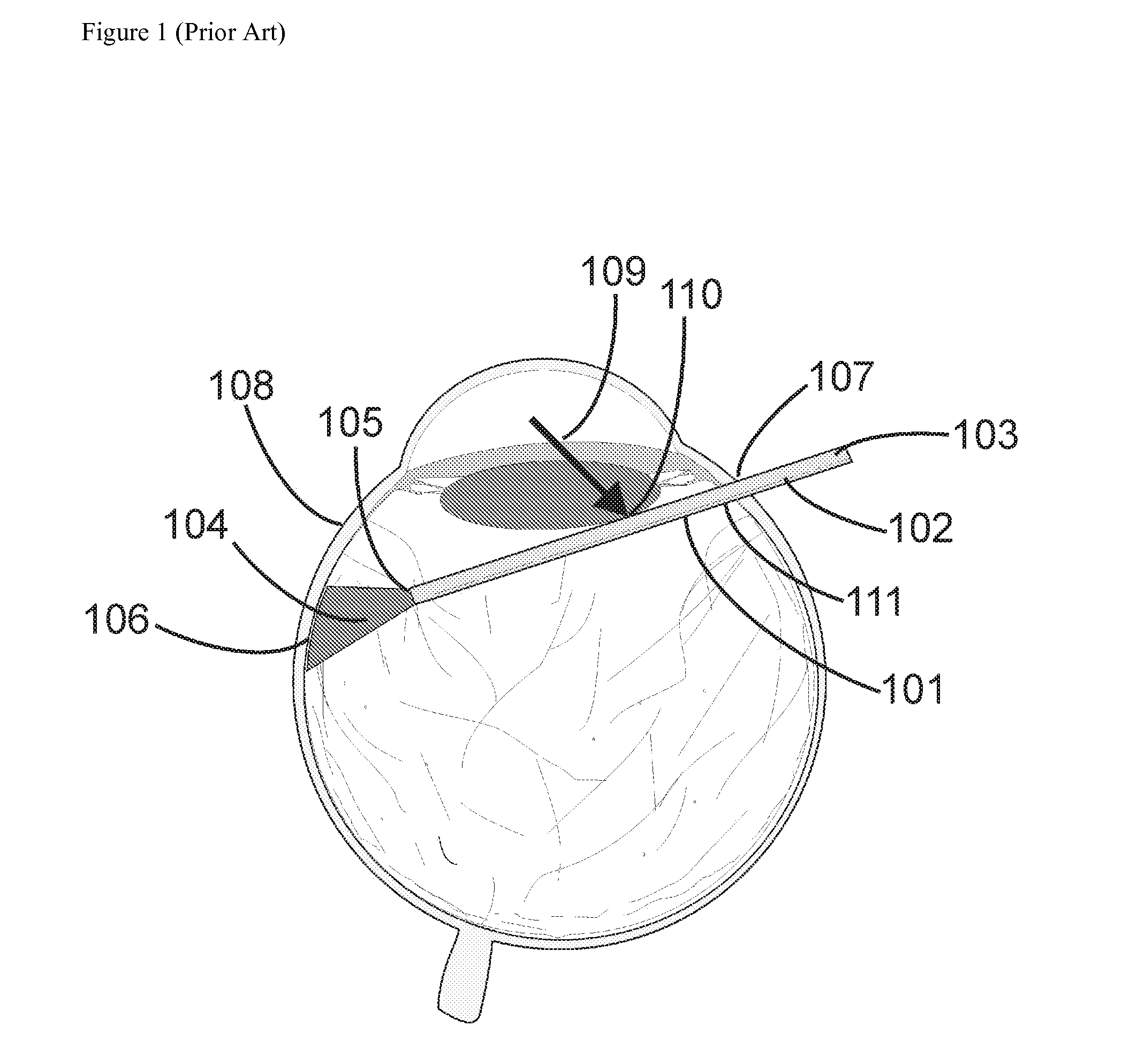
This reduction in intensity in turn reduces the effectiveness of the prior art laser probe 101.
But unfortunately these probes can be used only with great difficulty in modern small incision vitrectomy surgery using cannulae.
Even if the surgeon manages to force a curved laser probe through the cannula, the removal of the curved probe from the eye often causes the undesired effect of the cannula being removed from the eye as well.
But again, this type of laser probe is difficult to manipulate during surgery.
For a second example, to remove the probe from the eye, the second metal tube must be manually straightened, necessitating awkward motions on the part of the surgeon and placing the eye at risk of inadvertent injury.
Another shortcoming common to all three types of prior art laser probes described above is that all of these laser probes employ a rigid metal outer sleeve that is potentially traumatic to delicate intraocular structures.
Inadvertent contact with the lens or retina in particular can lead to serious physiological consequences.

Method used


Image

  • Steerable and flexibly curved probes
  • Steerable and flexibly curved probes
  • Steerable and flexibly curved probes

Examples


Embodiment Construction

[0027]The following is a description of several embodiments of various aspects of the invention. These embodiments are illustrative only. The invention is limited only by the scope of the claims that are appended hereto, and is by no means limited to particular examples described below.

[0028]The present invention is useful for many purposes. The anticipated field of use is generally referred to herein as “surgery.” However, the terms “surgery” and “surgical” should be understood in a broad sense, as also including diagnostic methods carried out internally, and related instruments, as well as minimally invasive procedures and instruments, or those employed through a small incision, such as in connection with catheterization and endoscopy. In addition, the invention is also adaptable to non-medical applications, such as non-medical endoscopy and boroscopy, and the use of the term “surgical” or like medical-related terms should not be understood as limiting the scope of the invention t...


PUM


Abstract

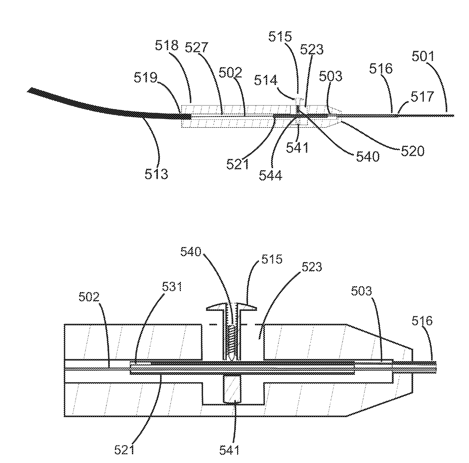
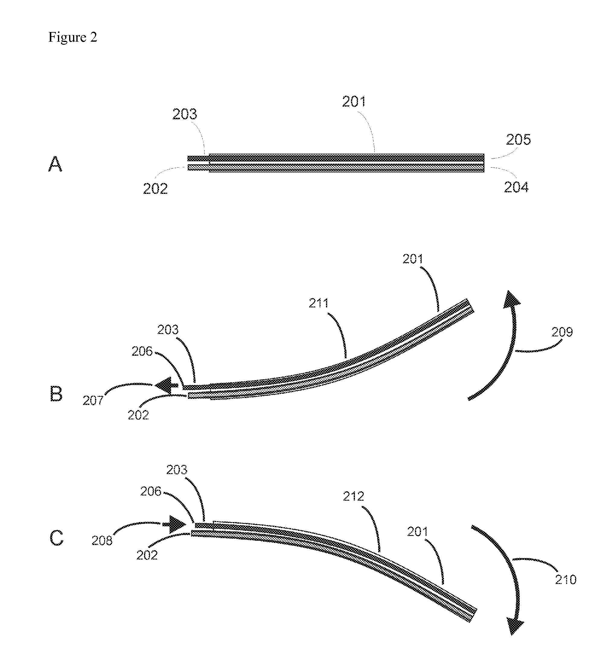
Steerable and flexibly curved probes are provided, primarily for A surgical applications. A probe with flexible distal portion is inserted through an incision or cannula and the flexible distal portion may be selectively bent or steered using a guide wire. The guide wire is extended through the probe on a radially offset axis, and affixed at its distal end to the distal end of the flexible distal portion. The curvature of the nitinol wire is induced by extending or retracting the wire from the proximal end of the flexible distal portion while the distal end of the guide wire remains affixed to the distal end of the probe. The guide wire is activated by a finger-actuated mechanism. A further embodiment is provided in which the guide wire is fixed at both ends of the flexible distal portion of the probe and has a normally curved conformation, and assumes such conformation after insertion through a straight cannula. Other embodiments and applications are similarly disclosed.

Description

CROSS-REFERENCE TO RELATED APPLICATIONS[0001]This application claims the benefit of the filing date of U.S. Provisional Application No. 60 / 887,635 (“Steerable Intraocular Laser”), filed Feb. 1, 2007, and U.S. Provisional Application No. 60 / 887,921 (“Flexible Curved Intraocular Laser Probe”), filed Feb. 2, 2007. The entire respective disclosures of each of said provisional patent applications are hereby incorporated by reference herein.BACKGROUND OF THE INVENTION[0002]1. Field of the Invention[0003]The invention concerns insertable probes, primarily in the surgical field, which can be steered or redirected after insertion. Several embodiments of the invention are in the form of steerable or flexibly curved microsurgical laser probes for use primarily in ophthalmic surgery. However, the invention also relates to insertable probes generally and has non-medical applications, for example, to non-medical endoscopy and boroscopy.[0004]2. Background of the Related Art[0005]A wide variety of...

Claims


Application Information

Patent Timeline
Patent Type & Authority Applications(United States)
IPC IPC(8): A61F9/011
CPCA61F9/008A61B18/22A61F2009/00863A61F9/00821
Inventor SPAIDE, RICHARD F.
Owner SPAIDE RICHARD F
Learn More