Anchors and methods for securing suture to bone

a technology applied in the field of anchors and methods for securing sutures to bone, can solve the problems of large force required to insert anchors into bone, broken anchors, broken insertion tools,

Active Publication Date: 2009-12-17
CAYENNE MEDICAL INC
View PDF21 Cites 164 Cited by
  • Summary
  • Abstract
  • Description
  • Claims
  • Application Information

AI Technical Summary

Benefits of technology

[0011]The anchor described in the current invention incorporates several features which make it simple and consistent for the surgeon to implant. In particular, the current designs allow the surgeon to adjust the tension on the suture strands, thus approximating the captured tissue to the anchor location prior to securing the anchor and suture. Additionally, when the anchor is locked into the bone, the tension on the suture and captured tissue does not change.
[0012]Another advantage of the current designs is that they eliminate the need for the surgeon to tie a knot. The performance of the knot is dependent upon many factors—the skill of the surgeon, the type of suture material, the ease of access to the knot location, etc. Tying a secure knot often requires several knots, such as a Duncan Loop backed up by alternating half-hitches. Each of these must be pulled tight with a knot pusher to secure them properly. Securing the suture between the anchor and bone is much less time consuming and less prone to surgeon error or variability.

Problems solved by technology

A high amount of interference results in a large force required to insert the anchor into the bone.
These large insertion forces (often imparted by a hammer or mallet) can result in broken anchors, broken insertion tools, or worse, damage to the bone itself.
This can result in under- or over-tensioning of the tissue against the bone.
The final step of securing the suture and tissue—tying a knot—has been shown to be a common source of anchor failure.
It is also a step that requires a great deal of practice and skill by the surgeon and time during the procedure itself.
This step can be tedious and difficult, depending on the angle of approach to the hole.
This results in the tissue not being pulled firmly against the bone surface and may result in inferior long-term repair strength.
Depending on the angle of approach and the location on the bone (such as inferior on the glenoid), it may be impossible to drill a deep enough hole to achieve the desired tension.
Since the barbed portion of the anchor is a full cylinder, it can require a great deal of force to insert into a smaller diameter hole, especially in hard bone.
If the anchor were to pull out of the bone, the metal could cause a great deal of damage rubbing against the articular surfaces—e.g. the humeral head and glenoid.

Method used


Image

  • Anchors and methods for securing suture to bone
  • Anchors and methods for securing suture to bone
  • Anchors and methods for securing suture to bone

Examples


Embodiment Construction

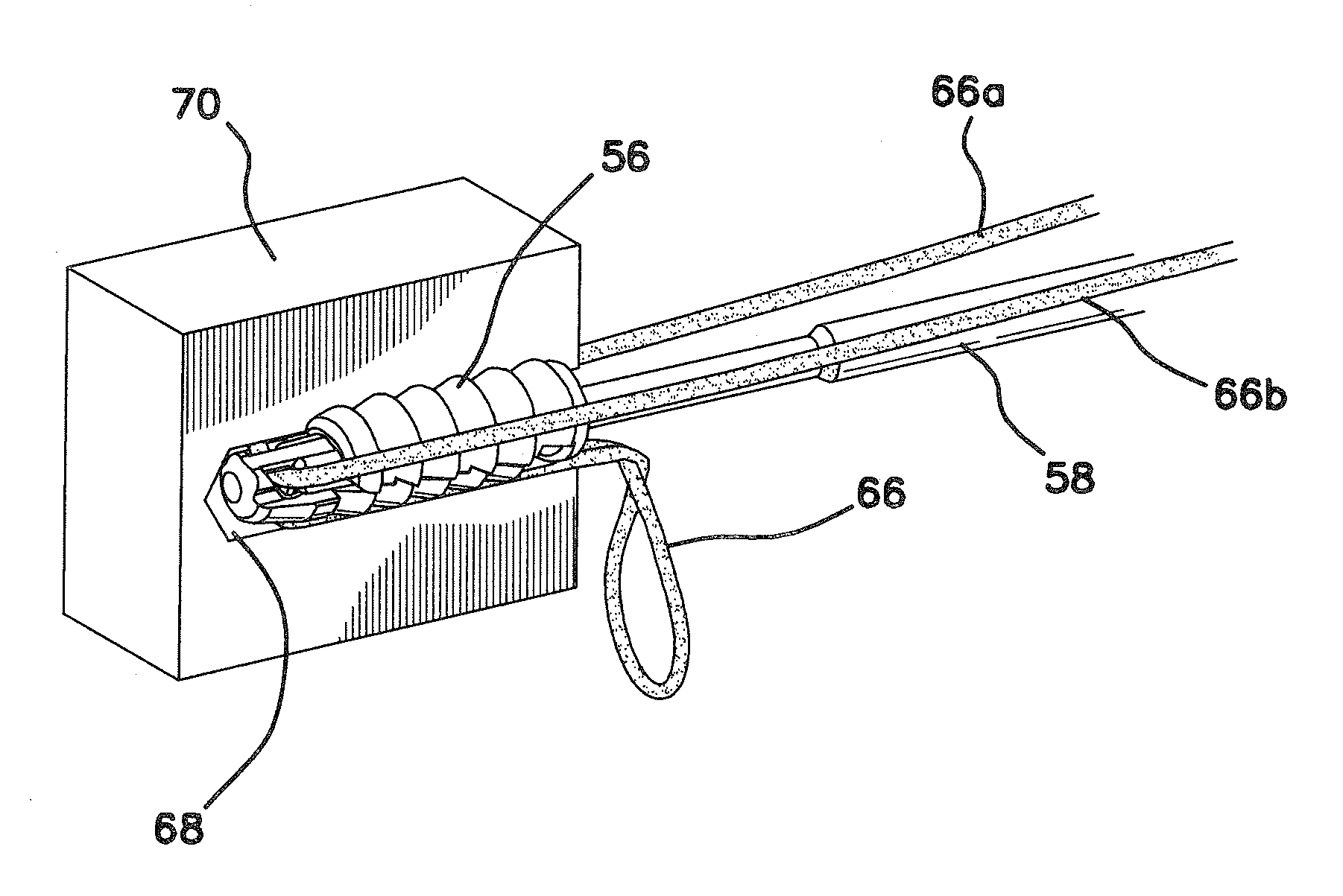
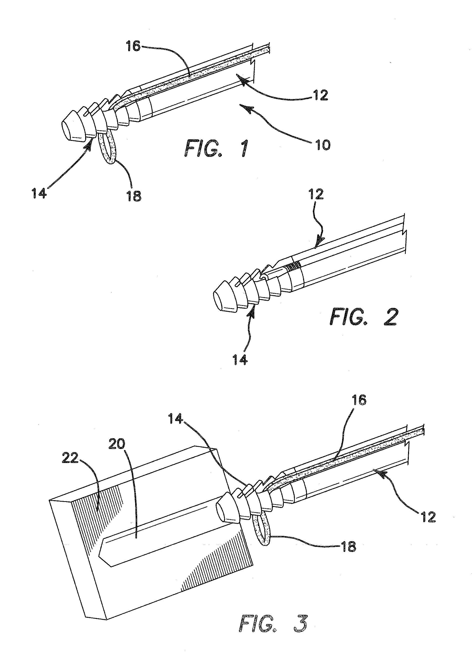
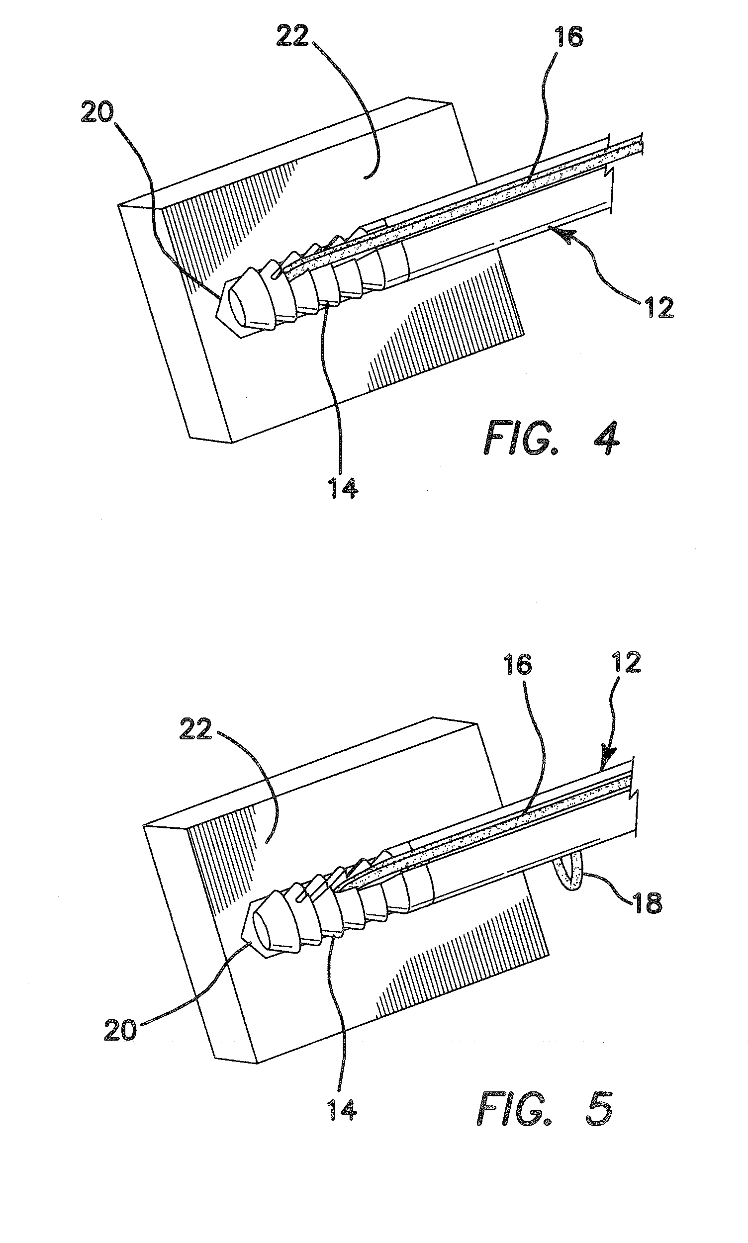
[0085]Referring now more particularly to the drawings, there is shown in FIGS. 1-5 the distal end of a “suture first” suture to bone implantable anchoring device 10. The device 10 comprises an inserter 12, and an implant 14 loaded on the tip of the inserter 12. Suture 16 is disposed along the inserter 12, as shown in FIG. 1, for example, and through the implant 14, with a loop 18 of suture extending therefrom. This loop 18 is the loop of suture which would extend through the tissue to be approximated to the bone, which is not shown, for clarity. Also not shown in this figure is a suture snare that is used to pull the suture loop 18 into a suture eyelet in the middle of the implant 14, which is illustrated and described below. The snare may comprise a loop of nitinol wire or suture, insert molded into a plastic pull-tab (not shown) which may be mounted on the shaft of the inserter 12. Once the suture strands are placed into the suture snare, the pull-tab is removed from the inserter ...


PUM


Abstract

A method for securing suture to bone comprises drilling a hole in a desired portion of bone at a desired procedural site, passing a strand of suture through a portion of soft tissue to be approximated to the portion of bone, and extending the free suture ends proximally from the soft tissue. The suture is loaded into an anchor implant. Using an inserter, on a distal end of which is attached the anchor implant, the anchor implant is manipulated into the bone hole. The suture is then tensioned to a desired level by pulling on the free suture ends, after the anchor implant is positioned in the bone hole. The free suture ends are wrapped about a suture cleat on an inserter handle once the desired tension level is achieved. A proximal anchor component is moved distally to engage with a distal anchor component to lock the anchor in place within the bone hole, and to lock the suture in place within the anchor. Then, the inserter is removed from the procedural site.

Description

[0001]This application is a continuation-in-part under 35 U.S.C. 120 of commonly assigned U.S. patent application Ser. No. 12 / 347,831, entitled Anchors and Method for Securing Suture to Bone, filed on Dec. 31, 2008, and also claims the benefit under 35 U.S.C. 119(e) of the filing date of Provisional U.S. Application Ser. No. 61 / 061,960, entitled Devices, Systems, and Methods for Material Fixation, filed on Jun. 16, 2008. Each of these prior patent applications are expressly incorporated herein by reference, in their entirety.BACKGROUND OF THE INVENTION[0002]The present invention is generally related to the field of suture anchors. There are many procedures, such as SLAP (Superior Labrum from Anterior to Posterior) and Bankart lesion repairs, or reconstruction of labral tissue to the glenoid rim, in which a surgeon needs to secure tissue in close contact with bone. Often the bone surface is roughened, and when tissue is pulled into intimate contact, the body's healing response will f...

Claims


Application Information

Patent Timeline
Patent Type & Authority Applications(United States)
IPC IPC(8): A61B17/04
CPCA61B17/0401A61B2017/0409A61B2017/0412A61B2017/0414A61B2019/307A61B2017/044A61B2017/0453A61B2017/0456A61B2017/0496A61B2017/0427A61B2090/037A61B17/0485
Inventor NASON, KEVIN S.HOOF, JORDAN A.
Owner CAYENNE MEDICAL INC
Why Eureka
Try Eureka