System and method for calculating location using a combination of odometry and landmarks

a technology applied in the field of system and method for calculating a location using a combination of odometry and landmarks, can solve the problems of insufficient study of the solution to overcome the problem of wheel skid, errors may occur, and accumulation of errors

Inactive Publication Date: 2009-12-17
ELECTRONICS & TELECOMM RES INST
View PDF1 Cites 52 Cited by
  • Summary
  • Abstract
  • Description
  • Claims
  • Application Information

AI Technical Summary

Benefits of technology

[0013]In addition, the present invention provides a technology of identifying the landmark all day long in a real-time manner using light sources of the landmar...

Problems solved by technology

This method of using odometry to obtain the location information has two significant problems.
Secondly, since odometry uses the revolution velocity of the wheel to measure distance, errors may occur when the wheel skids on a slippery ground surface depending on a ground condition.
Although odometry provides relatively accurate location information over a short distance, errors are accumulated as a driving distance increases, and a solution for overcoming this problem has not been sufficiently studied.
Thus, the location information cannot be reliably obtained using only odometry if there is no error correction method.
Generally, since the viewing angle of the camera is limited, an area in which the location can be obtained using the landmarks is limited.
It is not easy to arrange the landmarks to satisfy this condition, and in particular, this method is considered to be very inefficient from the viewpoint of cost, time, and aesthetical appearance when a location measurement system is constructed in a wide area space such as a market or a public building using only artificial landmarks.
In addition, when the landmark is temporarily obscured by obstacles such as visitors or customers, the location information cannot be appropriately obtained.
Also, since the image signal input through the camera is influenced by various conditions such as a distance between the landmark and the camera, a direction, and illumination, it is difficult to obtain stable recognition performance in a common indoor environment.
In particular, since image signals become weak during the night, it is nearly impossible to ...

Method used


Image

  • System and method for calculating location using a combination of odometry and landmarks
  • System and method for calculating location using a combination of odometry and landmarks
  • System and method for calculating location using a combination of odometry and landmarks

Examples


Embodiment Construction

[0033]Hereinafter, exemplary embodiments of the present invention will be described in detail with reference to the accompanying drawings.

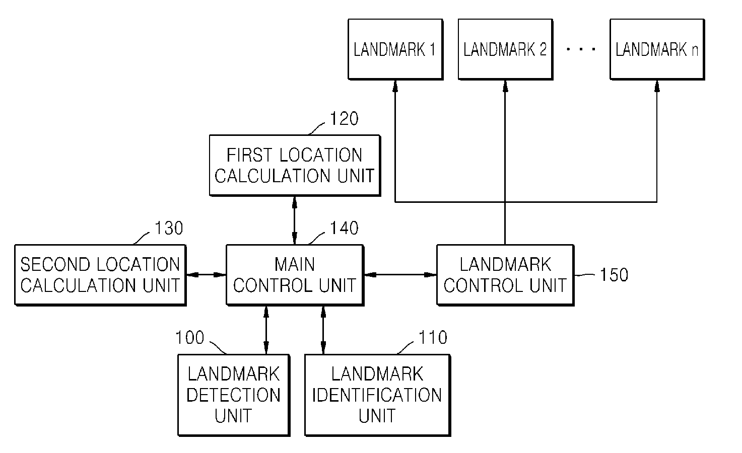
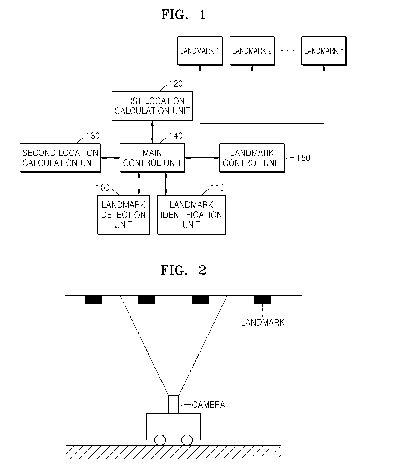
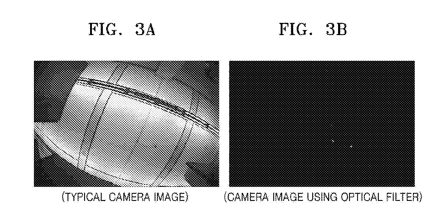
[0034]FIG. 1 is a block diagram illustrating components of a system for calculating a location of a mobile robot in a real-time manner according to an exemplary embodiment of the present invention. FIG. 2 is a schematic diagram for describing a process of photographing landmarks performed by a mobile robot according to an exemplary embodiment of the present invention. FIG. 3A is a photograph taken by a typical camera installed in a mobile robot, and FIG. 3B is a photograph taken by a camera installed in a mobile robot using an optical filter according to an exemplary embodiment of the present invention;

[0035]FIG. 2 shows a process of obtaining images in a landmark detection unit 100 of FIG. 1, and FIGS. 3A and 3B show images obtained through the process of FIG. 2. They will be described in association with FIG. 1.

[0036]Referring to FIG. 1, the sys...


PUM


Abstract

Disclosed is a system and method for calculation a location in a real-time manner using a combination of odometry and artificial landmarks. The system for calculating a location comprising a landmark detection unit detecting an image coordinates value of the artificial landmark corresponding to a location in a two-dimensional image coordinate system with respect to a mobile robot from an image obtained by photographing a specific space where the artificial landmarks are provided; a landmark identification unit comparing a predicted image value of the artificial landmark, obtained by converting a location coordinates value of the artificial landmark into an image coordinates value corresponding to the location in the two-dimensional image coordinate system with respect to a location coordinates value corresponding to a location in an actual three-dimensional spatial coordinate system of the mobile robot, with an image coordinates value detected by the landmark detection unit to detect the location coordinates value of the artificial landmark; a first location calculation unit calculating a current location coordinates value of the mobile robot using a predetermined location calculation algorithm based on the image coordinates value detected by the landmark detection unit and the location coordinates value detected by the landmark identification unit; a second location calculation unit calculating a current location coordinates value of the mobile robot using a predetermined location calculation algorithm based on odometry information of the mobile robot; and a main control unit updating the current location coordinates value of the mobile robot, using the location coordinates value calculated by the first location calculation unit when the location coordinates value calculated by the first location calculation unit exists, or using the location coordinate value obtained from the second location calculation unit when the location coordinates value calculated by the first location calculation unit does not exist.

Description

CROSS-REFERENCE TO RELATED PATENT APPLICATION[0001]This application claims the benefit of Korean Patent Application No. 10-2006-70838, filed on Jul. 27, 2006, in the Korean Intellectual Property Office, the disclosure of which is incorporated herein in its entirety by reference.BACKGROUND OF THE INVENTION[0002]1. Field of the Invention[0003]The present invention relates to a system and method for calculating a location using a combination of odometry and landmarks, and more particularly, to a system and method for calculating a location using a combination of odometry and landmarks in a real-time manner during movement of a mobile robot.[0004]2. Description of the Related Art[0005]In order to allow a mobile robot to make a routing plan to a destination in an indoor room and perform automatic driving, the mobile robot must recognize its location in an indoor room beforehand. A method of using an odometer of a wheel installed in the robot in order to obtain position information is kno...

Claims


Application Information

Patent Timeline
IPC IPC(8): G06F7/00
CPCG01C21/00G01C22/02G05D1/0272G05D1/0234G01S5/163B25J9/10
Inventor LEE, JAE-YEONGCHAE, HEESUNGYU, WON-PIL
Owner ELECTRONICS & TELECOMM RES INST
Why Eureka
Try Eureka