
Procedure and device for improving the maneuverability of an aircraft during the approach to landing and flare-out phases

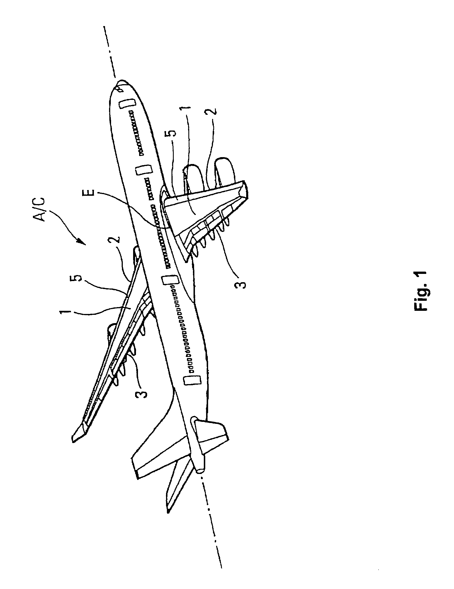
a technology for aircraft and flareout phases, applied in automatic actuation, process and machine control, instruments, etc., can solve the problem of less maneuverability of aircraft in this configuration, and achieve the effect of eliminating these drawbacks

Active Publication Date: 2009-12-24
AIRBUS OPERATIONS (SAS)
View PDF21 Cites 10 Cited by
  • Summary
  • Abstract
  • Description
  • Claims
  • Application Information

AI Technical Summary

Benefits of technology

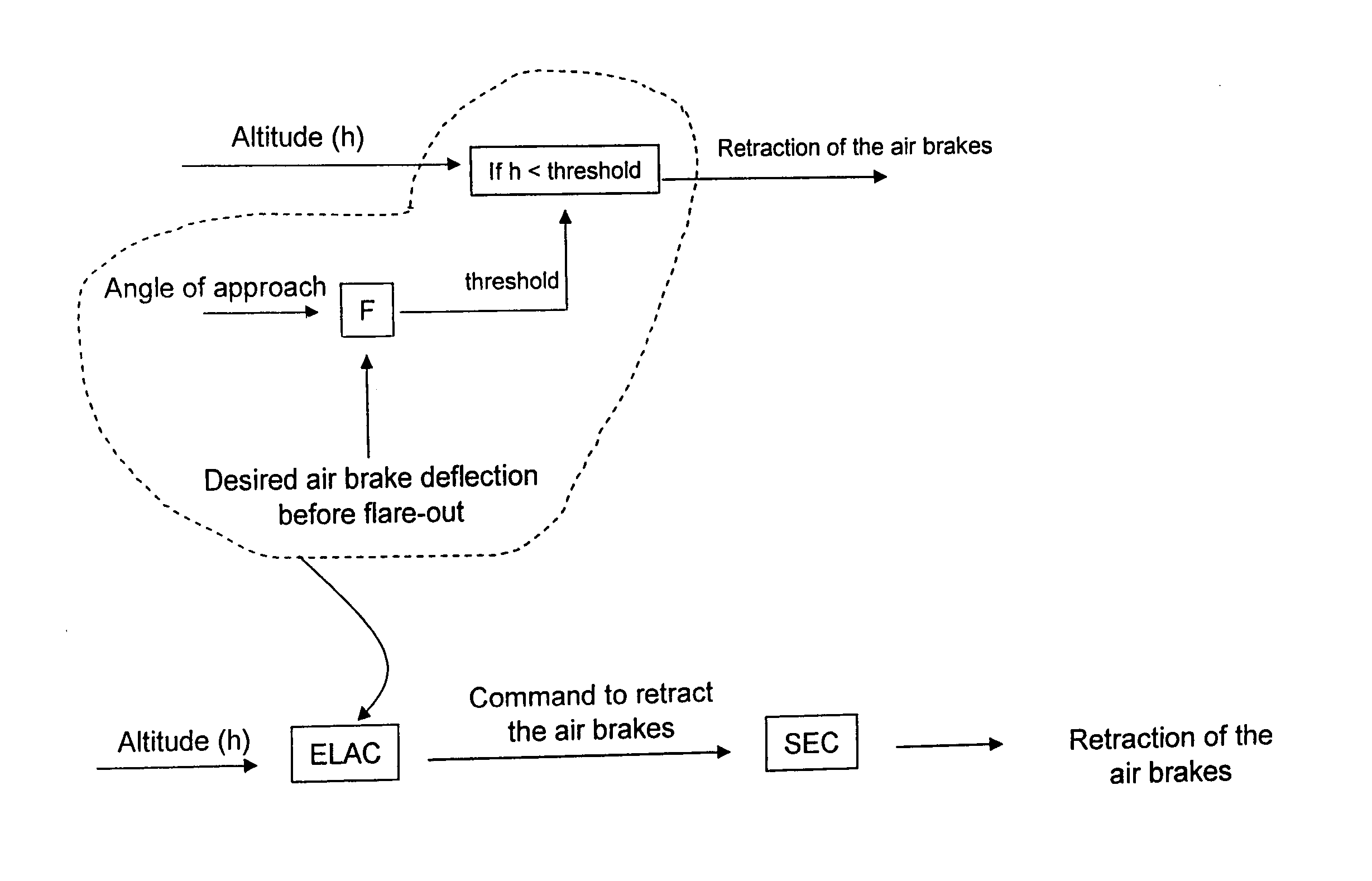
The present invention is about a process and device for improving the maneuverability of an aircraft during the approach to landing and then flare-out phases, using air brakes. The invention addresses the problem of the aircraft being unable to maintain a stable angle of incidence during the approach and flare-out phases, which can result in a loss of control and safety. The invention involves placing the air brakes in a first deployed position during the approach phase and automatically transitioning them to a second, more retracted position during the approach at a steep flight path angle. This retraction of the air brakes allows for a flare-out that maintains the same angle of incidence as if the aircraft were at a normal approach angle. The invention also includes the use of trailing edge flaps that can be put into a first deployed position during the approach phase and automatically transition to a second, more deployed position during the flare-out phase. The control of the air brakes and the flaps can be interconnected, and the device can be computer-controlled. The technical effect of the invention is to improve the stability and control of the aircraft during the approach and flare-out phases, ensuring safety and efficiency.

Problems solved by technology

The inventors have however observed that at the time of flare-out (when the pilot pulls back on the control stick (or wheel) to redress the aircraft before touchdown on the runway), the aircraft is in this configuration less maneuverable.

Method used


Image

  • Procedure and device for improving the maneuverability of an aircraft during the approach to landing and flare-out phases
  • Procedure and device for improving the maneuverability of an aircraft during the approach to landing and flare-out phases
  • Procedure and device for improving the maneuverability of an aircraft during the approach to landing and flare-out phases

Examples


Embodiment Construction

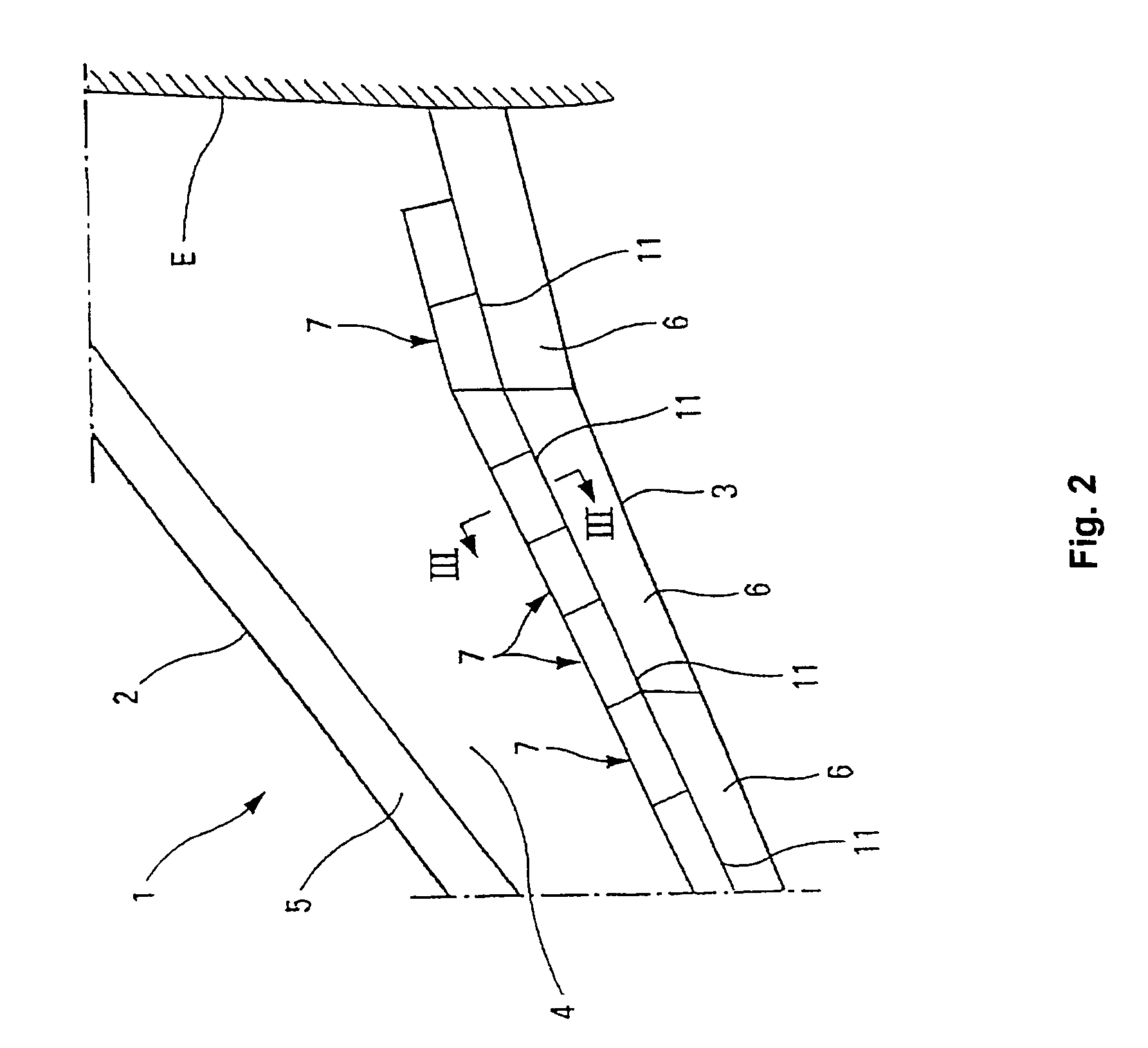
[0072]As is shown in FIG. 3, each deflecting flap 7 is hinged, on the side of its leading edge 8, to the structure 9 of wing 1 around an axis 10, parallel to the leading edge 8.

[0073]In the retracted position represented in FIGS. 2 and 3, the trailing edge 11 of each deflecting flap 7 is supported by a trailing edge flap 6 and the top side 12 of the deflecting flap 7 provides the aerodynamic continuity between wing top 4 of wing 1 and the top side 13 of flap 6.

[0074]Furthermore, each deflecting flap 7 is connected to the structure 9 of wing 1 by a slanting leg constituted by a jack 14, the ends 15 and 16 of which are hinged on said structure 9 and said deflecting flap 7 respectively.

[0075]In retracted position of deflecting flap 7, as described in FIGS. 2 and 3, the jack 14 exerts a force in order to maintain the flap in retracted position.

[0076]When jack 14 is activated for extension, the deflecting flap 7 pivots progressively around axis 10 while deploying. As shown in FIG. 4, for...


PUM


Abstract

The process improves the maneuverability of an aircraft during the approach to landing and then flare-out phases, the aircraft being equipped with air brakes. According to the process, the air brakes are put in a first deployed position during the approach phase, and as a function of a representative parameter of a given altitude and in case of a steep angle approach, they are actuated to transition to a second more retracted position than the first position so as to achieve a flare-out allowing to essentially maintain the same angle of incidence, corresponding in case of a steep angle approach to achieve a flare-out with habitual exterior piloting references during the flare-out phase.

Description

CROSS REFERENCE TO RELATED APPLICATIONS[0001]This application is a divisional of and claims the benefit of priority under 35 USC § 120 from U.S. application Ser. No. 11 / 182,864, filed Jul. 18, 2005, the entire contents of which are incorporated herein by reference. This application also claims benefit of priority under 35 USC § 119 (e) from U.S. Provisional Application Ser. No. 60 / 614,394, filed Sep. 30, 2004, and is based upon and claims the benefit of priority under 35 USC § 119 from the French Patent Application No. 0407952, filed Jul. 16, 2004.BACKGROUND OF THE INVENTION[0002]This invention concerns the improvement of the maneuverability of an aircraft during the approach to landing and then flare-out phases with the aid of an appropriate control of the spoiler flaps, also called air brakes.[0003]By “improving the maneuverability of an aircraft” one understands here that which facilitates its operation.DISCUSSION OF THE BACKGROUND[0004]The main portion of approaches to landing, ...

Claims


Application Information

Patent Timeline
Patent Type & Authority Applications(United States)
IPC IPC(8): G05D1/06
CPCB64C9/20B64C9/32Y02T50/32B64C19/02G05D1/0676B64C13/16Y02T50/30
Inventor BOISSENIN, STEPHANEROSAY, JACQUES
Owner AIRBUS OPERATIONS (SAS)
Learn More