Current sensor arrangement for measurement of currents in a primary conductor

a current sensor and conductor technology, applied in the direction of amplifiers, base element modifications, instruments, etc., can solve the problems of inability to achieve the effect of reducing inductance, high cost-effectiveness of sensors, and reducing inductan

Inactive Publication Date: 2009-12-24
VACUUMSCHMELZE GMBH & CO KG
View PDF12 Cites 32 Cited by
  • Summary
  • Abstract
  • Description
  • Claims
  • Application Information

AI Technical Summary

Benefits of technology

[0012]One embodiment disclosed herein relates to a current sensor arrangement for measurement of a primary current in a primary conductor disclosed herein, has the following components: a ferromagnetic core for magnetic coupling of the primary conductor to a secondary conductor; a controlled voltage source which is connected to the secondary conductor; a drive device, which is connected to the secondary conductor, for regular remagnetization of the ferromagnetic core, with the drive device having a controlled voltage source which is connected to the secondary conductor and is designed to prov...

Problems solved by technology

These sensors are highly cost-effective, but are relatively inaccurate.
Although the inductance could be reduced, and the sensor frequency increased, by using small coils and coil cores, this is frequently not feasible because of the increased susceptibility of relatively small cores to disturbance.
One problem with the known flux gate sensors is the high maximum current draw resulting from the periodic complete remagnetization of the magnet system of the flux gate sensor, which results i...

Method used


Image

  • Current sensor arrangement for measurement of currents in a primary conductor
  • Current sensor arrangement for measurement of currents in a primary conductor
  • Current sensor arrangement for measurement of currents in a primary conductor

Examples


Embodiment Construction

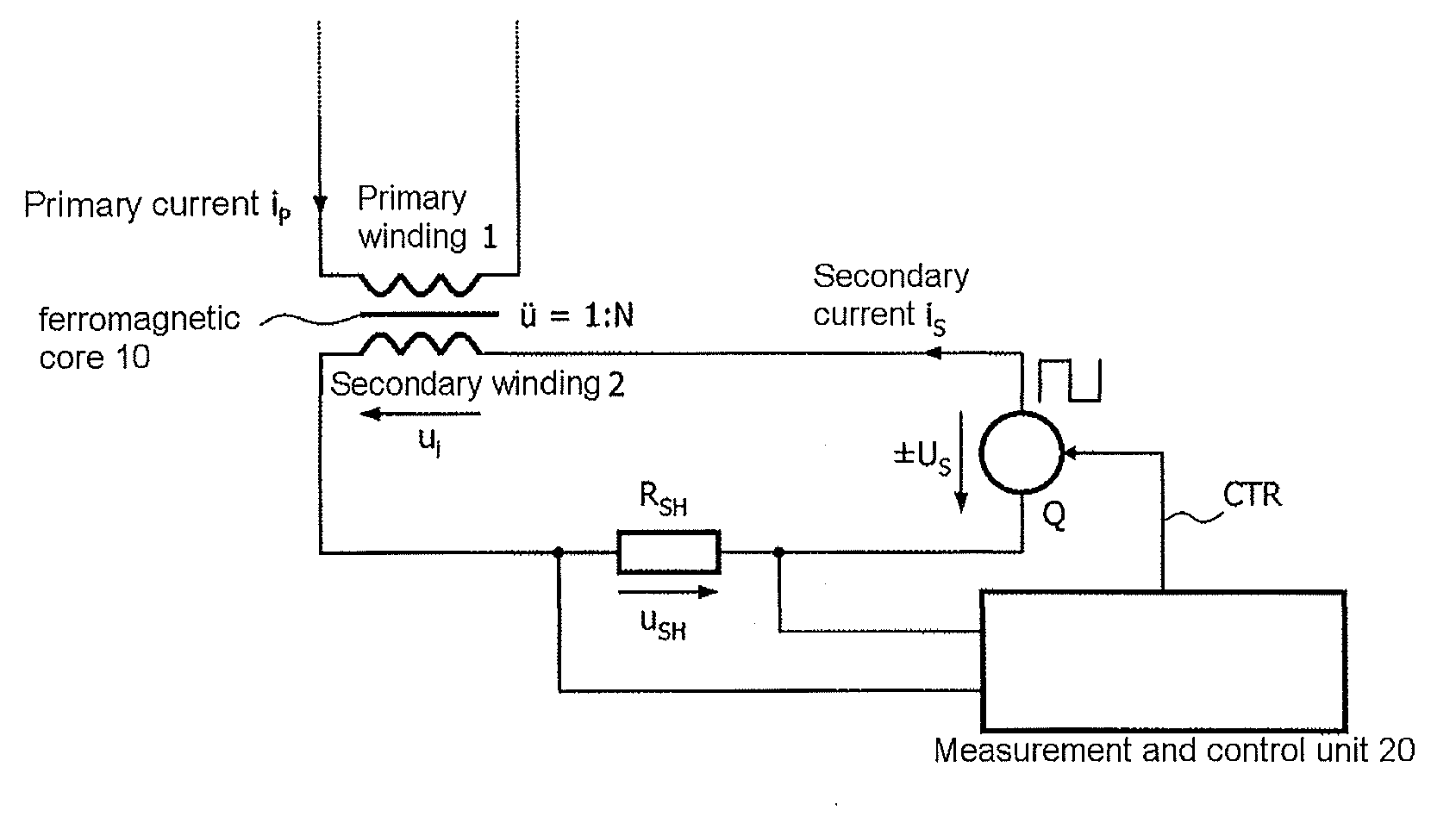
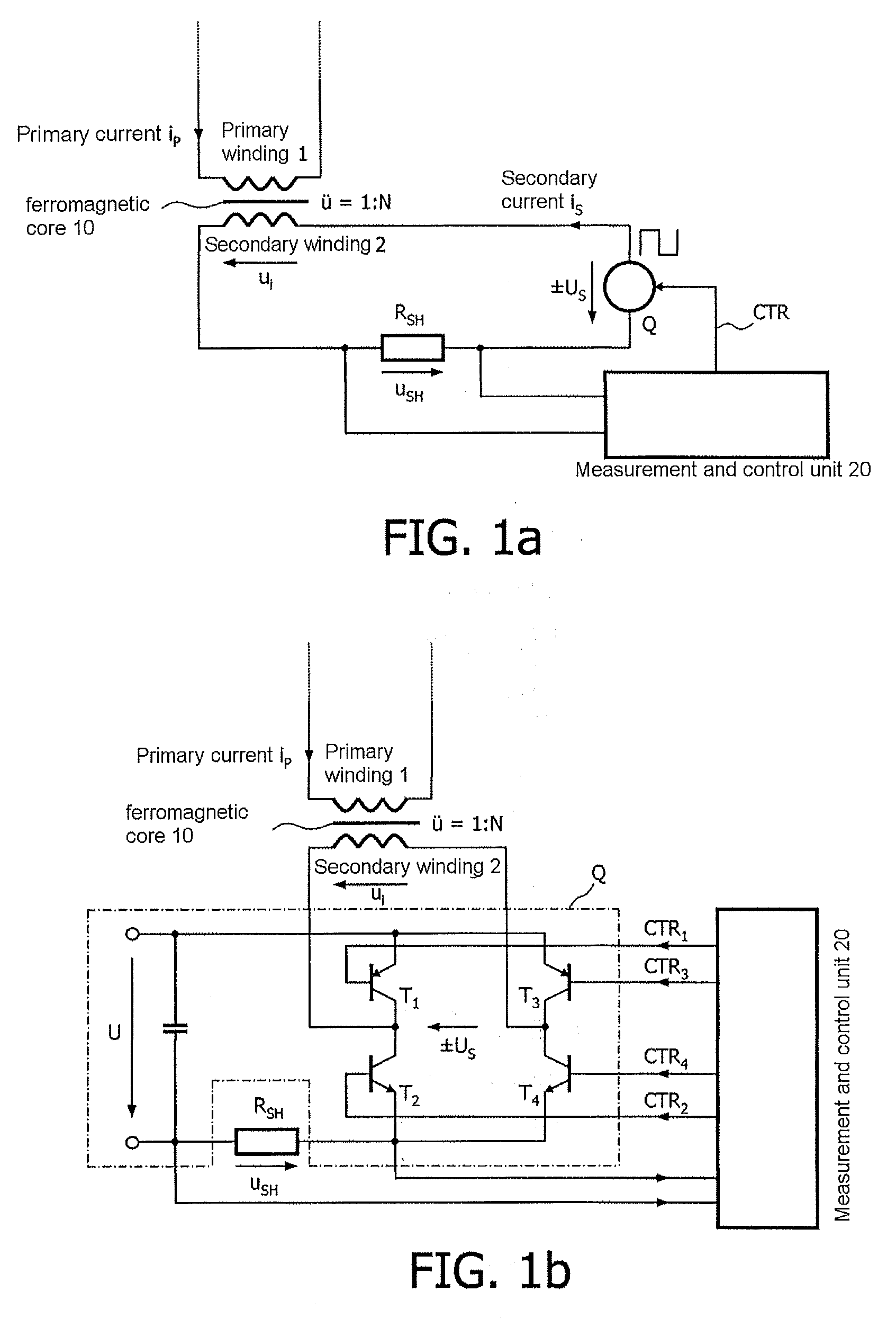
[0025]FIG. 1a uses a diagram to show the basic design of a compensation current sensor without any hysteresis error. The current to be measured (primary current iP) flows through a primary winding 1 which is magnetically coupled to a secondary winding 2 (number of turns N) via a soft-magnetic and, for example, unslotted core 10. By way of example, the primary winding 1 may comprise one single turn, that is to say the primary winding 1 is formed from a conductor which is passed through the core 10 (number of turns 1). The secondary winding 2 is connected in series with a controlled voltage source Q, which produces the secondary current iS through the secondary winding and which is capable of reversing polarity. In order to measure the secondary current iS, a shunt resistor RSH is connected between the secondary winding 2 and the voltage source Q. The voltage USH across the shunt resistor RSH is supplied to a measurement and control unit 20, which also provides a control signal CTR fo...


PUM


Abstract

A method and current sensor arrangement for measurement of a primary current in a primary conductor which is magnetically coupled to a secondary conductor via a ferromagnetic core, with a voltage of a specific amplitude being applied to the secondary conductor, such that a secondary current flows for remagnetization of the ferromagnetic core, and the secondary current is measured during the remagnetization of the core, in order to obtain a first measured value. The voltage polarity is then reversed such that a secondary current flows for renewed remagnetization of the ferromagnetic core, and the secondary current is measured during the remagnetization of the core, in order to obtain a second measured value. The primary current is calculated as a function of the first and of the second measured value, with the polarity reversal being carried out at least once at a time which occurs before that time at which the ferromagnetic core reaches its saturation magnetization.

Description

BACKGROUND[0001]1. Field[0002]Disclosed herein is a current sensor arrangement for measurement of currents in a primary conductor over a wide measurement range.[0003]2. Description of Related Art[0004]On the one hand, so-called direct-mapping current sensors are known for non-contacting, and therefore electrically floating measurement of the level of an electric current in a conductor, which sensors sense the magnetic flux caused by the current, for example by means of a Hall sensor in a slotted magnetic circuit, and produce a signal which is proportional to the current level. These sensors are highly cost-effective, but are relatively inaccurate. Direct-mapping current sensors are so-called open-loop current sensors which do not contain a closed control loop.[0005]Furthermore, so-called closed-loop current sensors are known, in which a closed control loop is used to continuously produce a magnetic opposing field of the same magnitude as the current to be measured as a result of whi...

Claims


Application Information

Patent Timeline
IPC IPC(8): G01R19/00
CPCG01R19/20G01R15/185
Inventor KOCH, RALF
Owner VACUUMSCHMELZE GMBH & CO KG
Why Eureka
Try Eureka