Electromagnet device and electromagnetic contactor

a technology of electromagnetic contactor and electromagnetic device, which is applied in the direction of magnets, contact mechanisms, magnetic bodies, etc., can solve the problems of degrading the function of shading coil, increasing the amount of material to be used, and poor productivity, so as to improve the efficiency of shading coil, reduce the size of the core, and improve the effect of durability

Inactive Publication Date: 2009-12-24
FUJI ELECTRIC FA COMPONENTS & SYST CO LTD
View PDF1 Cites 21 Cited by
  • Summary
  • Abstract
  • Description
  • Claims
  • Application Information

AI Technical Summary

Benefits of technology

[0020]With the electromagnetic contactor according to the invention, the core of an electromagnet device can be downsized, so that the electromagnetic contactor can be made compact and its durability can be made enhanced.
[0021]As is apparent from the foregoing exp

Problems solved by technology

This increases the amount of material to be used.
Nevertheless, there is a problem of taking time in attaching and welding for securing the shading coil that results in poor productivity.
Moreover, there is an increase in electric resistance at the section where both ends of the bar-like material for

Method used


Image

  • Electromagnet device and electromagnetic contactor
  • Electromagnet device and electromagnetic contactor
  • Electromagnet device and electromagnetic contactor

Examples


first embodiment

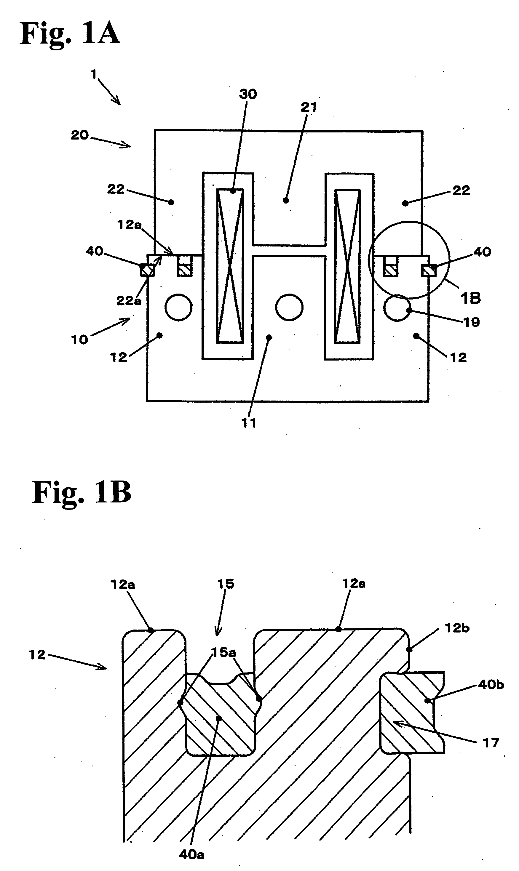
[0033]FIGS. 1A and 1B are views schematically showing a structure of an electromagnet device according to the invention. FIG. 1A is a front view in which the electromagnet device is viewed from the direction orthogonal to both of the direction of driving a movable core and the direction of arranging legs forming each of the movable and a stationary core. FIG. 1B is a view showing the section 1B in FIG. 1A with the section 1B being enlarged.

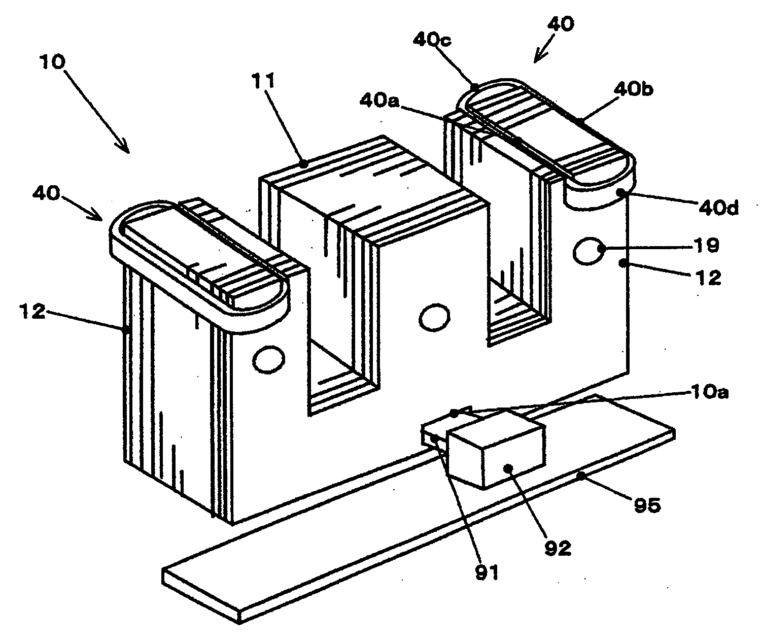
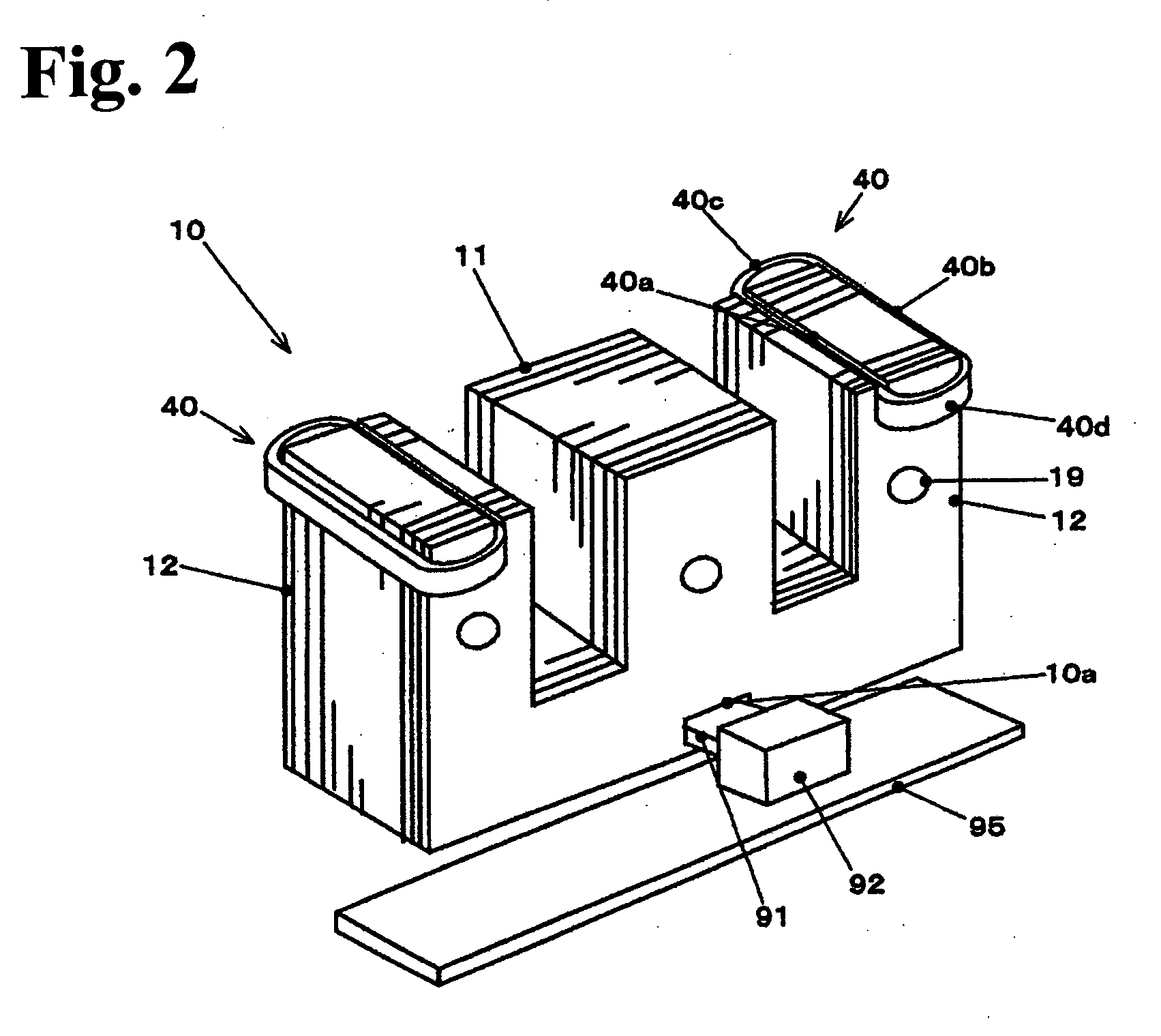
[0034]FIG. 2 is a perspective view showing the stationary core in the electromagnet device shown in FIGS. 1A and 1B.

[0035]The electromagnet device 1 shown in FIGS. 1A and 1B is, like the electromagnet device shown in FIGS. 5A and 5B, formed of a stationary core 10, a movable core 20, an operating coil 30 and a shading coil 40. Each of the stationary core 10 and the movable core 20 is an E-shaped core formed with approximately E-shaped flat rolled silicon steel sheets laminated and secured by rivets 19. The E-shaped stationary core 10 has a central...

second embodiment

[0050]FIG. 4 is a front view illustrating the structure of an electromagnetic contactor according to the invention.

[0051]The electromagnetic contactor 50, as shown in FIG. 4, has a lower frame 60 and an upper frame 70 as a lower part and an upper part, respectively, of a case that is divided into two. Inside them, components such as the electromagnet device 1 and a contactor device 80 are provided.

[0052]The electromagnet device 1 is what is explained with reference to FIGS. 1A and 1B and other drawings, and is formed of the stationary core 10, the movable core 20, the operating coil 30 and the shading coil 40. The stationary core 10 is contained in the lower frame in a floating state. The stationary core 10 has a through hole formed so as to penetrate the stationary core 10 in its thickness direction. Into the through hole, the supporting plate 91 is inserted. The elastic body 92 of an elastic material such as rubber is attached to each end of the supporting plate 91 protruding from...


PUM


Abstract

A core for an electromagnetic device includes a yoke and at least two legs extending from the yoke. The yoke and at least two legs are formed of steel plates laminated together. Each of the legs has a free end face forming a magnetic pole face, a first groove extending from the magnetic pole face and a second magnetic groove on a side face thereof. Also, the core includes a shading coil having a metal ring shape, and including a first linear section and a second linear section extending in parallel with each other. A part of the first linear section is accommodated in the first groove, and a part of the second linear section is accommodated in the second groove and locked therein. A bottom face of the second groove forms an angle with respect to a bottom face of the first groove.

Description

BACKGROUND OF THE INVENTION AND RELATED ART STATEMENT[0001]The present invention relates to an electromagnet device mounted on a unit such as an electromagnetic contactor and an electromagnetic contactor provided with an electromagnet device and particularly to a device such as an electromagnet device having a core provided with a shading coil.[0002]First, an example of an electromagnet device will be explained which has a core provided with a shading coil. A shading coil is a coil provided in a single-phase AC electromagnet for suppressing variations in an electromagnetic attractive force due to variations in alternating magnetic flux together with noises and vibrations.[0003]FIGS. 5A and 5B are views schematically showing an example of an electromagnet device. FIG. 5A is a front view in which the electromagnet device is viewed from the direction orthogonal to both of the direction of driving a movable core and the direction of arranging legs forming each of the movable and a stati...

Claims


Application Information

Patent Timeline
IPC IPC(8): H01H3/00H01F3/02
CPCH01F7/1205H01H51/06H01H50/546H01H50/46
Inventor SUZUKI, KENJINAKA, YASUHIROTAKAYA, KOUETSUOHGAMI, TOSHIKATSU
Owner FUJI ELECTRIC FA COMPONENTS & SYST CO LTD
Why Eureka
Try Eureka