Spherical motor positioning

a technology of rotating motors and positioning plates, which is applied in the direction of antennas, dynamo-electric components, dynamo-electric machines, etc., can solve the problems of significant limitations in real-world applications, inability to provide systems in which significant portions of the turning radius of various axes are unavailable, and movement in the first axis to be limited to 90 degrees

Active Publication Date: 2009-12-24
VIASAT INC
View PDF13 Cites 10 Cited by
  • Summary
  • Abstract
  • Description
  • Claims
  • Application Information

AI Technical Summary

Problems solved by technology

Even with diligent design consideration, it is often impossible to provide systems in which significant portions of the turning radius of various axes are unavailable due to physical interference.
For example, a single axis rotational system may allow for 120 degrees of movement in that axis, but adding a second axis of rotation having 60 degrees of movement cause the movement in the first axis to be limited to 90 degrees because of physical interference between the two systems.
This limitation on the rotational degree of freedom in each axis can lead to some significant limitations in real world applications.
By way of example, below-horizon aiming of parabolic antennas, which may require severe angular freedom of motion, may be impossible if multiple axes of rotation are also desired.
Furthermore, the ability to rotate a subject object about an axis of its own, or provide for other functions of such a subject object (i.e. power and data transfer), may also be impeded or otherwise complicated by the electro-mechanical systems necessary for rotation in all axes.
For example, providing power and / or data transfer to these subject objects may be interfered with either because of either physical interference by the rotational systems, or the extreme nature of desired rotations when actually achievable.

Method used


Image

  • Spherical motor positioning
  • Spherical motor positioning
  • Spherical motor positioning

Examples


Embodiment Construction

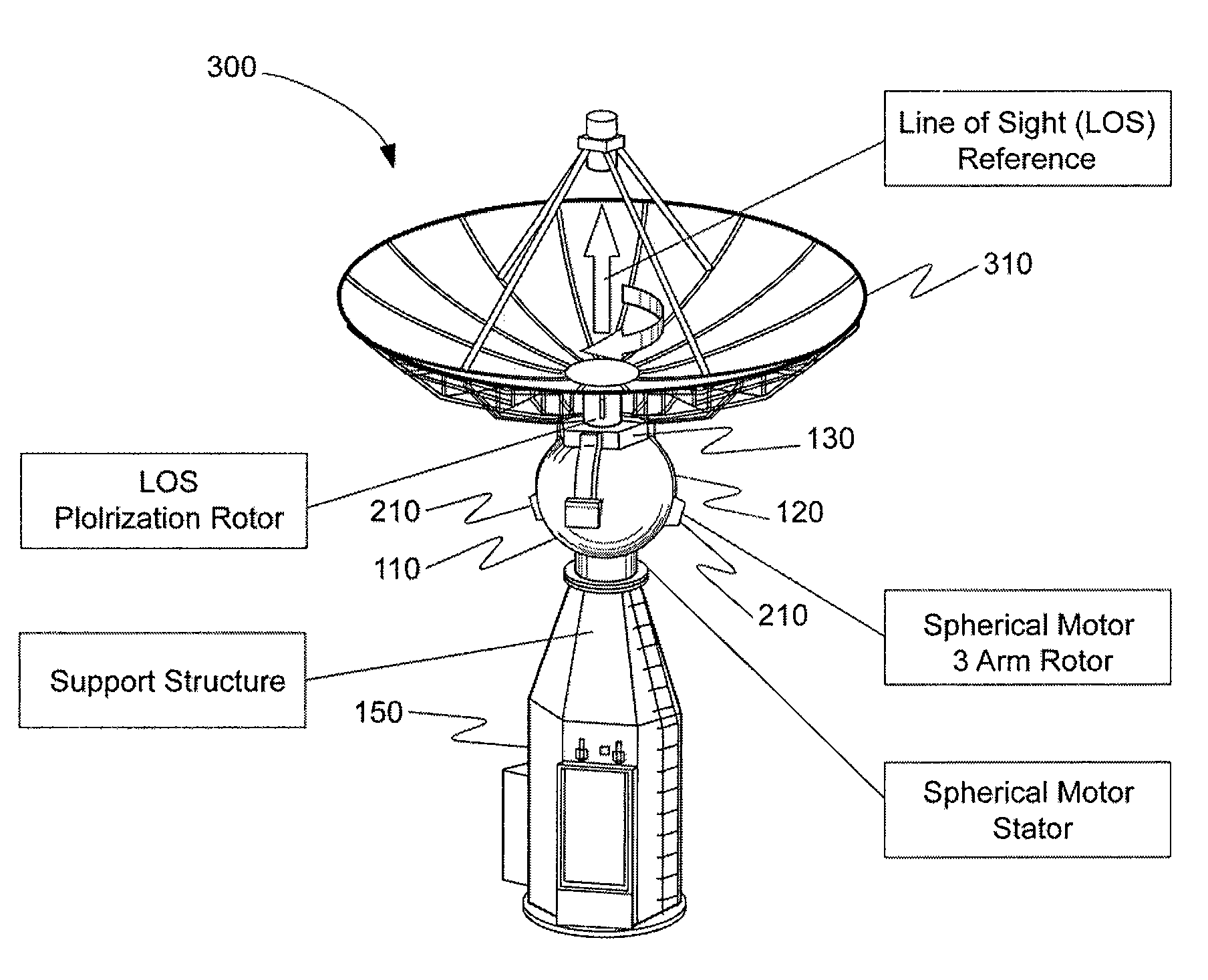
[0031]The ensuing description provides exemplary embodiments only, and is not intended to limit the scope, applicability or configuration of the disclosure. Rather, the ensuing description of the exemplary embodiments will provide those skilled in the art with an enabling description for implementing one or more exemplary embodiments. It being understood that various changes may be made in the function and arrangement of elements without departing from the spirit and scope of the invention as set forth in the appended claims.

[0032]Specific details are given in the following description to provide a thorough understanding of the embodiments. However, it will be understood by one of ordinary skill in the art that the embodiments may be practiced without these specific details. For example, circuits, systems, networks, processes, and other elements in the invention may be shown as components in block diagram form in order not to obscure the embodiments in unnecessary detail. In other i...


PUM


Abstract

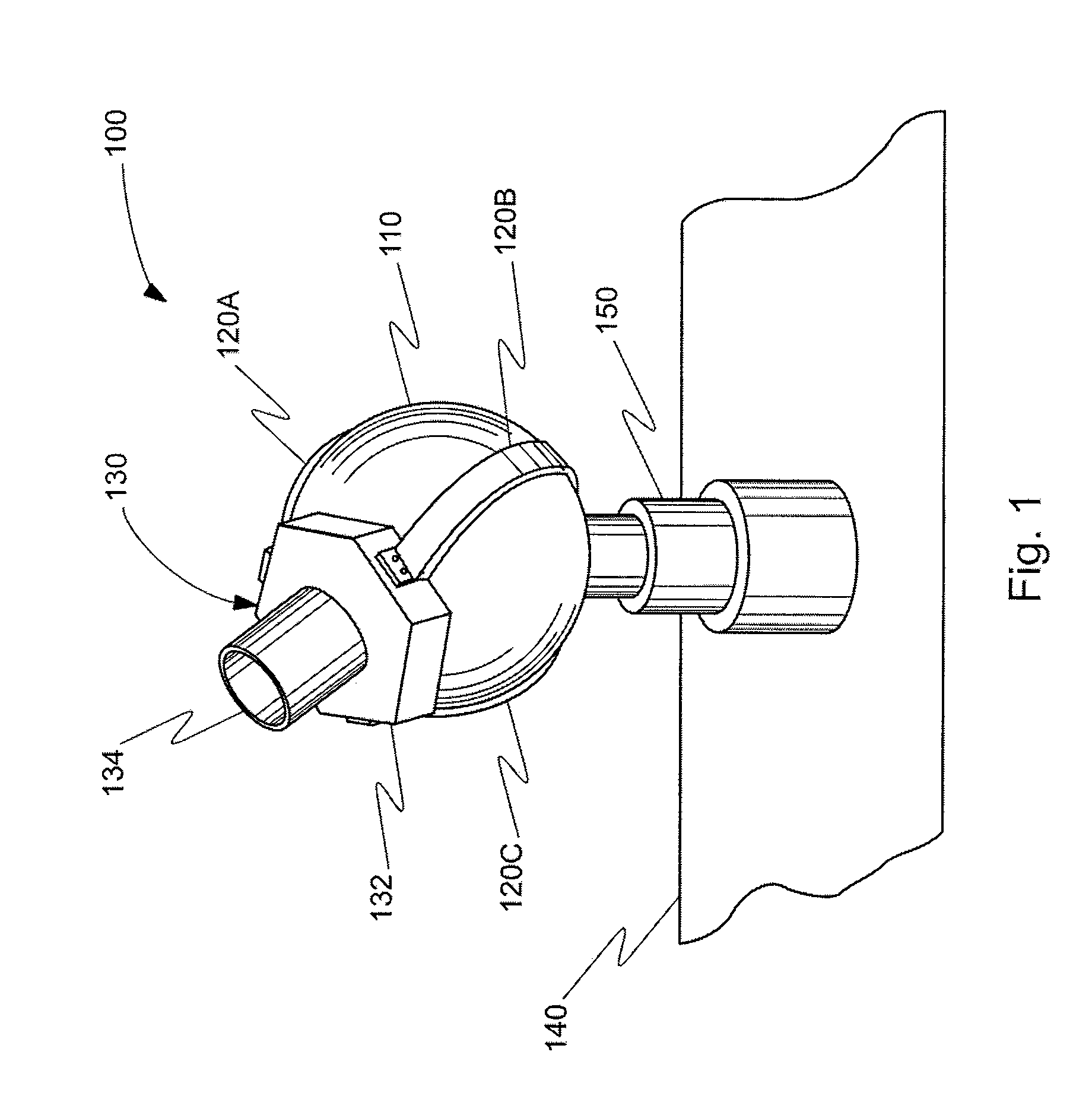
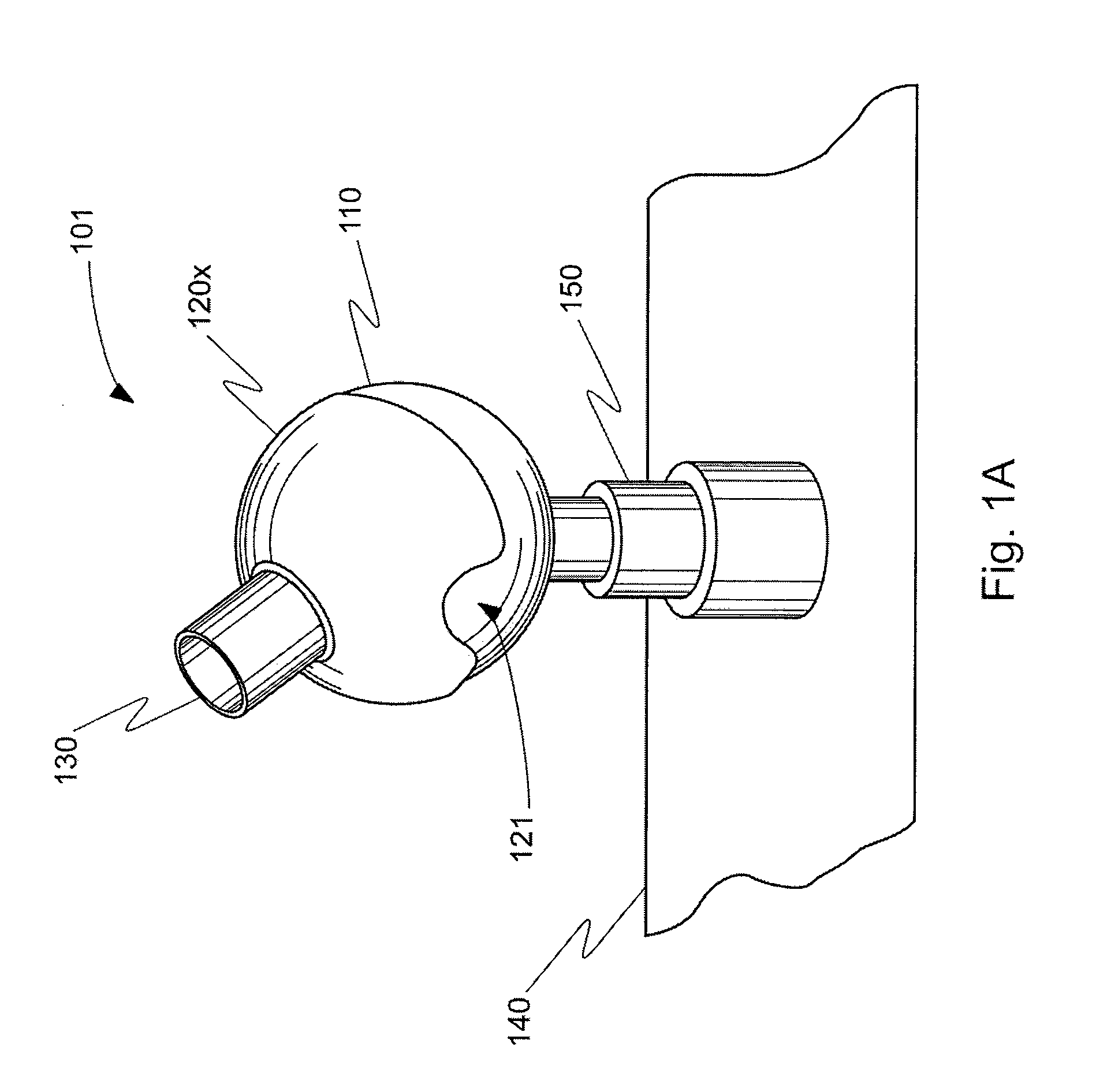
According to the invention, a system for rotating a parabolic antenna about a central point is disclosed. The system may include a support member, a spherical structure, and at least one arm. The support member may be coupled with a surface and may also be coupled with the support member. The spherical structure may be at least partially spherical in shape about the central point. The spherical structure may include a first plurality of magnets. The at least one arm may be in proximity to the spherical structure and may also include a second plurality of magnets. The at least one arm may be coupled with the parabolic antenna, and at least a portion of the magnets in either one of, or both of, the first plurality of magnets and the second plurality of magnets may be configured to be selectively activated to rotate the arms about the central point.

Description

CROSS-REFERENCE TO RELATED APPLICATIONS[0001]This application claims priority to Provisional U.S. Patent Application No. 60 / 917,258 filed May 10, 2007, entitled “SPHERICAL MOTOR POSITIONING,” the entire disclosure of which is hereby incorporated by reference, for all purposes, as if fully set forth herein.BACKGROUND OF THE INVENTION[0002]This invention relates generally to reorientation of objects via electro-mechanical means. More specifically the invention relates to rotating parabolic antennas.[0003]Existing electro-mechanical systems employed to reorient objects usually involves providing rotational motion of objects about certain axes. Each desired axis of rotation capability typically requires an independent electro-mechanical system. For example, a single axis of rotation is easily achieved using a singular electro-mechanical system which may include a chassis, motors, gearboxes, shafts, and bearings. Two axes of rotation necessitate an additional electro-mechanical system. F...

Claims


Application Information

Patent Timeline
Patent Type & Authority Applications(United States)
IPC IPC(8): H01Q3/00
CPCH01Q1/125H01Q3/02H01Q3/08H02K7/09H02K2201/03H02K2201/18H02N15/00H02K16/00H02K41/031
Inventor BLALOCK, E. MITCHELL
Owner VIASAT INC
Why Eureka
Try Eureka