Passive parabolic antenna, wireless communication system and method of boosting signal strength of a subscriber module antenna

a passive parabolic antenna and subscriber module technology, applied in the direction of radiating element housings, protective materials, electrical devices, etc., can solve the problems of increasing cost and interference with other communications systems, and achieve the effect of boosting signal strength

Inactive Publication Date: 2010-09-21
MCCOWN JAMES CHARLES
View PDF11 Cites 16 Cited by
  • Summary
  • Abstract
  • Description
  • Claims
  • Application Information

AI Technical Summary

Problems solved by technology

However, increasing power may cause interference to other communications systems and increases cost.

Method used


Image

  • Passive parabolic antenna, wireless communication system and method of boosting signal strength of a subscriber module antenna
  • Passive parabolic antenna, wireless communication system and method of boosting signal strength of a subscriber module antenna
  • Passive parabolic antenna, wireless communication system and method of boosting signal strength of a subscriber module antenna

Examples


Embodiment Construction

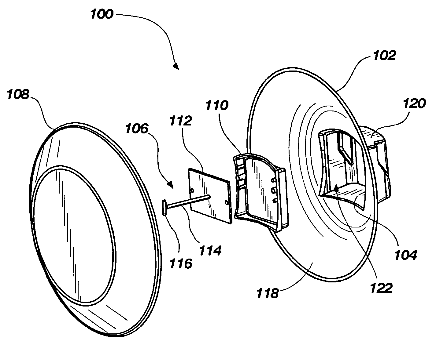
[0027]The invention is a passive parabolic antenna for use with conventional subscriber module radio antennas. The passive parabolic antenna forms a resonant cavity coupling device that couples to the existing internal patch antenna of a conventional subscriber module radio antenna. A method of boosting signal strength of a conventional subscriber module radio antenna using the passive parabolic antenna and a wireless communication system including same is also disclosed.

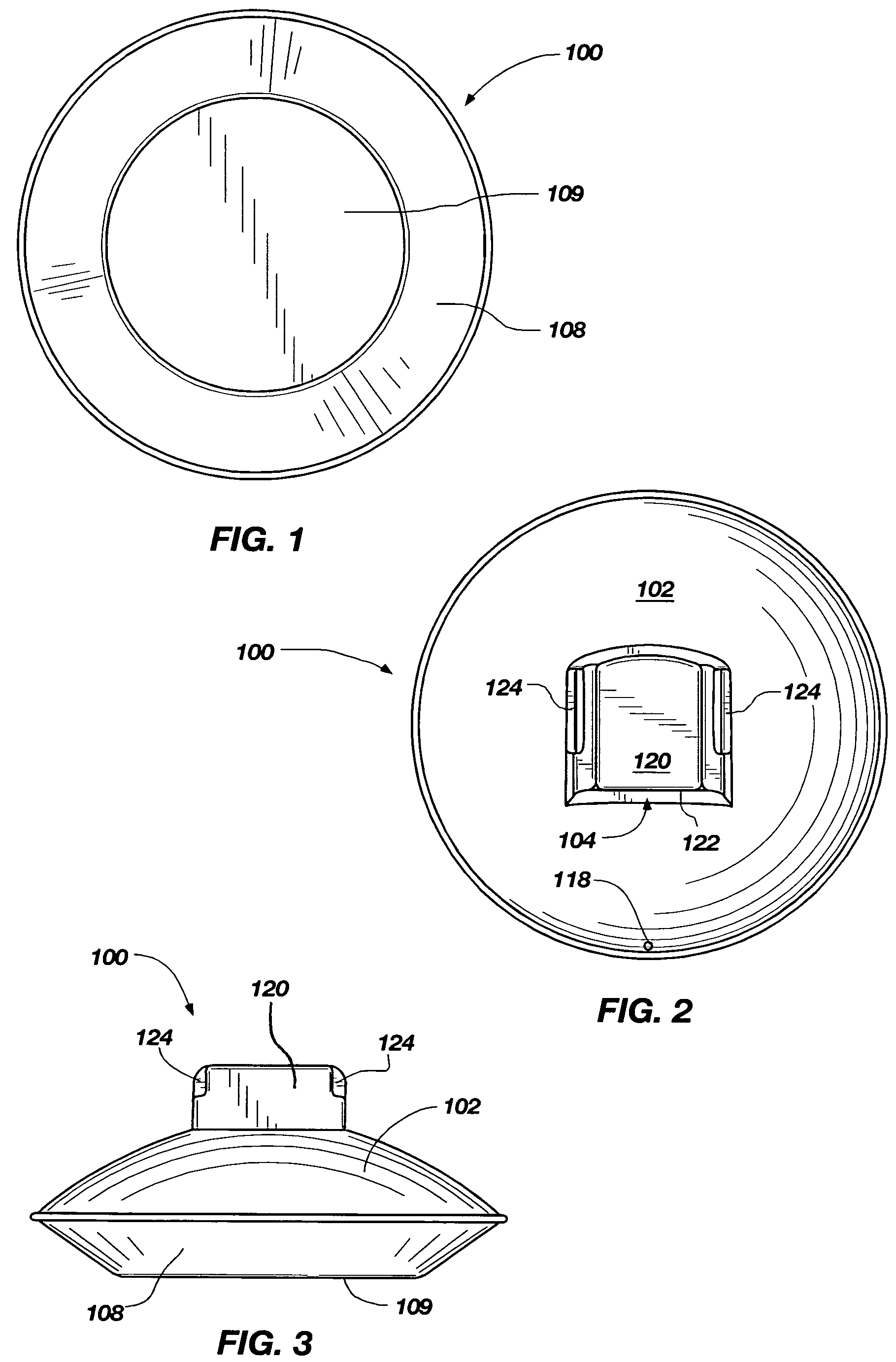
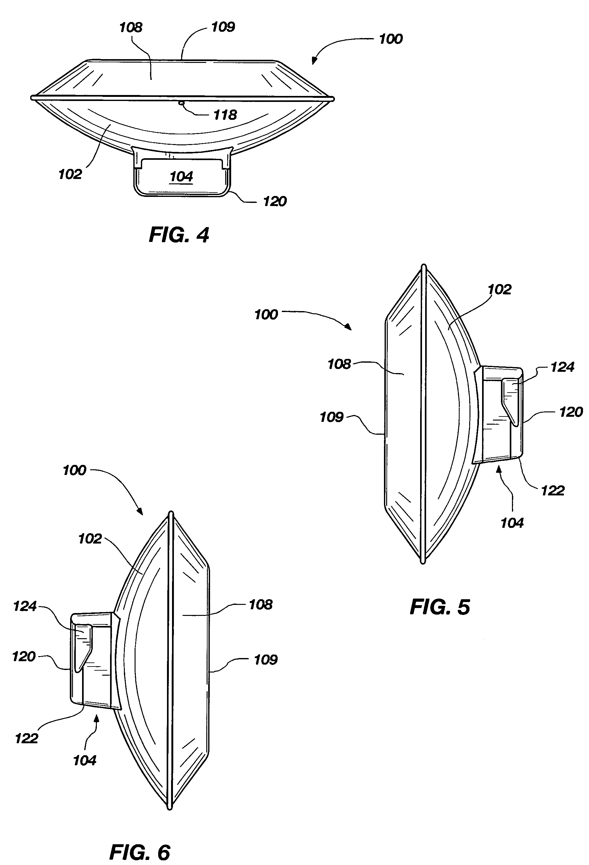
[0028]FIGS. 1-3 illustrate front, back and top views, respectively of an embodiment of an assembled passive parabolic antenna 100 according to the present invention. The passive parabolic antenna 100 may include a parabolic reflector 102 mated with an antenna cover 108. The antenna cover may include a covering 120 for a subscriber module pocket 104 at the bottom end 122 of the covering 120. Antenna cover 108 may be generally dish-shaped with a flat portion 109. According to another embodiment, the passive parabolic ...


PUM


Abstract

The invention is a passive parabolic antenna system for use with conventional subscriber module radio antennas. The passive parabolic antenna system includes a microwave feed assembly that forms a resonant cavity coupling device for coupling to an internal patch antenna of a conventional subscriber module radio antenna. A method of boosting signal strength of a conventional subscriber module radio antenna and a wireless communication system are also disclosed.

Description

CROSS-REFERENCE TO RELATED APPLICATIONS[0001]This nonprovisional patent application claims benefit and priority under 35 U.S.C. §119(e) of the filing of U.S. Provisional Patent Application Ser. No. 60 / 816,700 filed on Jun. 27, 2006, titled “PASSIVE PARABOLIC ANTENNA SYSTEM AND METHOD FOR BOOSTING SIGNAL STRENGTH OF A SUBSCRIBER MODULE ANTENNA”, the contents of which are incorporated herein by reference for all purposes. This nonprovisional patent application is also related to U.S. Design patent application Ser. No. 29 / 264,719 filed on Aug. 16, 2006, titled: “PARABOLIC ANTENNA”, the contents of which are also incorporated herein by reference for all purposes.BACKGROUND OF THE INVENTION[0002]1. Field of the Invention[0003]The present invention relates generally to antennas for wireless communication systems. More particularly, this invention relates to a passive parabolic antenna system and method for boosting signal strength of subscriber module radio antennas.[0004]2. Description o...

Claims


Application Information

Patent Timeline
Patent Type & Authority Patents(United States)
IPC IPC(8): H01Q19/18
CPCH01Q1/40H01Q19/13
Inventor MCCOWN, JAMES CHARLES
Owner MCCOWN JAMES CHARLES
Why Eureka
Try Eureka