Liquid crystal panel and liquid crystal display apparatus

a liquid crystal display and liquid crystal technology, applied in non-linear optics, instruments, optics, etc., can solve the problems of low contrast ratio in front and oblique directions, and the enhancement of contrast using reflective polarizing plates has not been realized, so as to achieve excellent display properties and remarkable high contrast ratio in front direction

Active Publication Date: 2009-12-24
NITTO DENKO CORP
View PDF16 Cites 11 Cited by
  • Summary
  • Abstract
  • Description
  • Claims
  • Application Information

AI Technical Summary

Benefits of technology

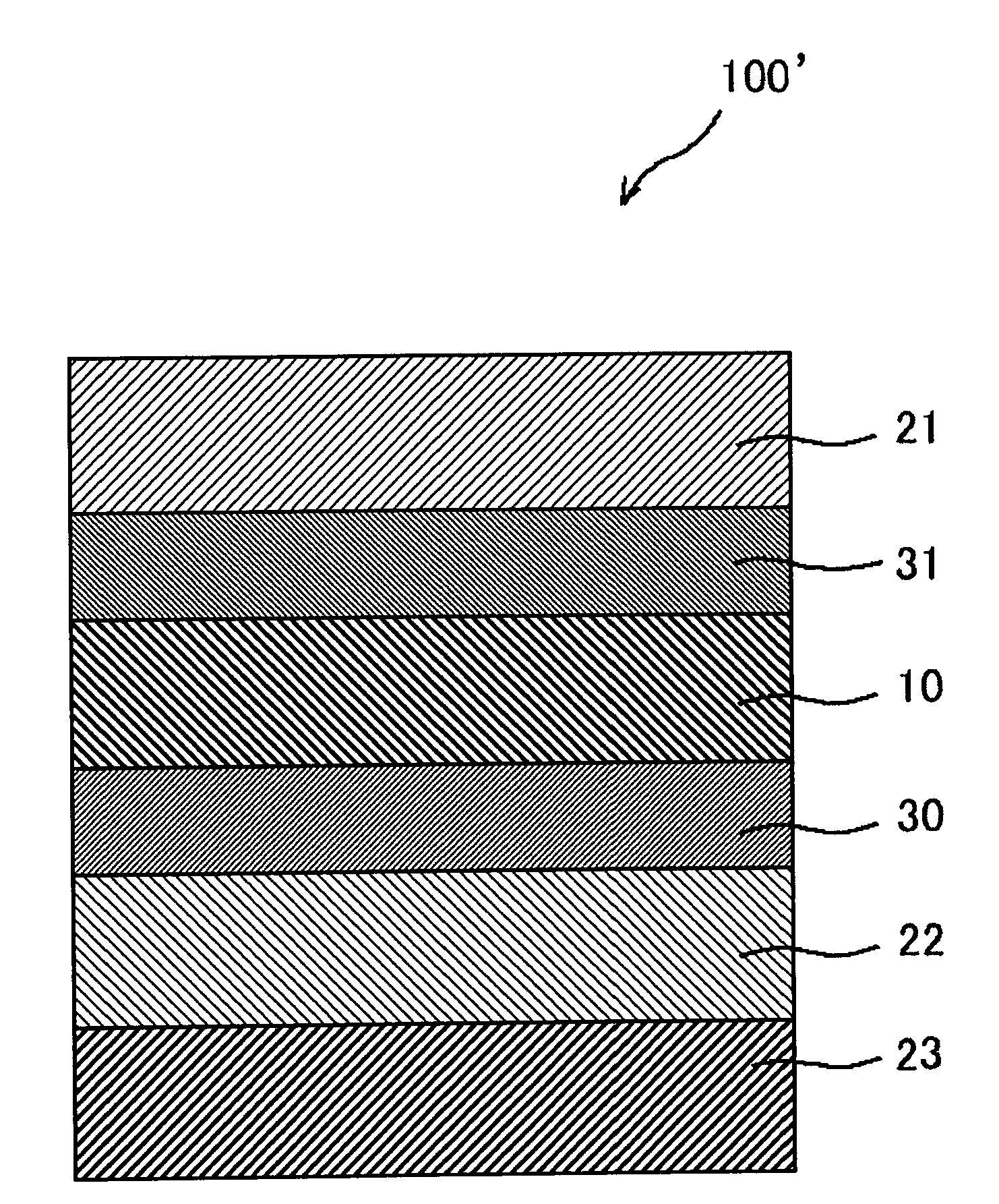
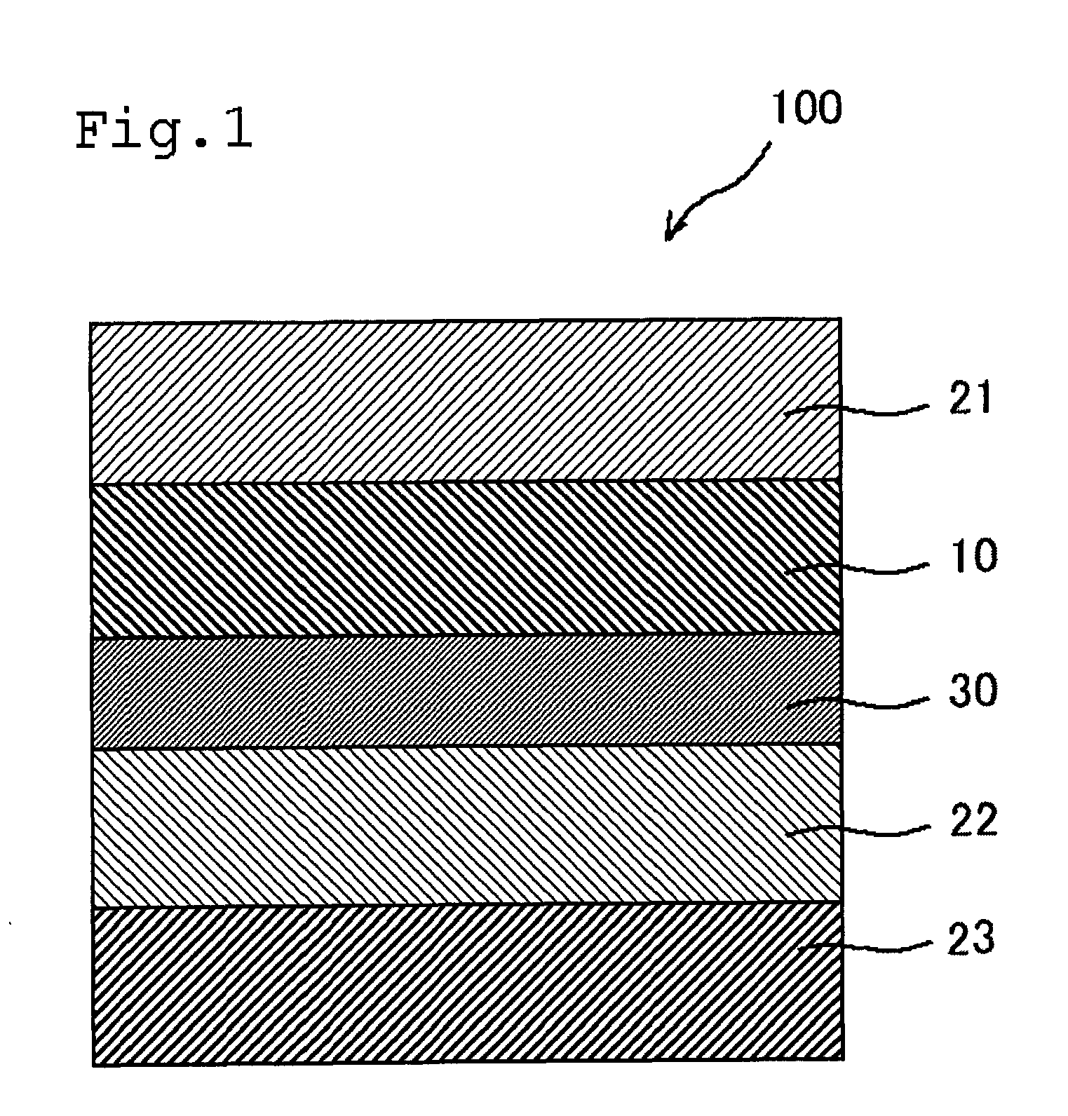
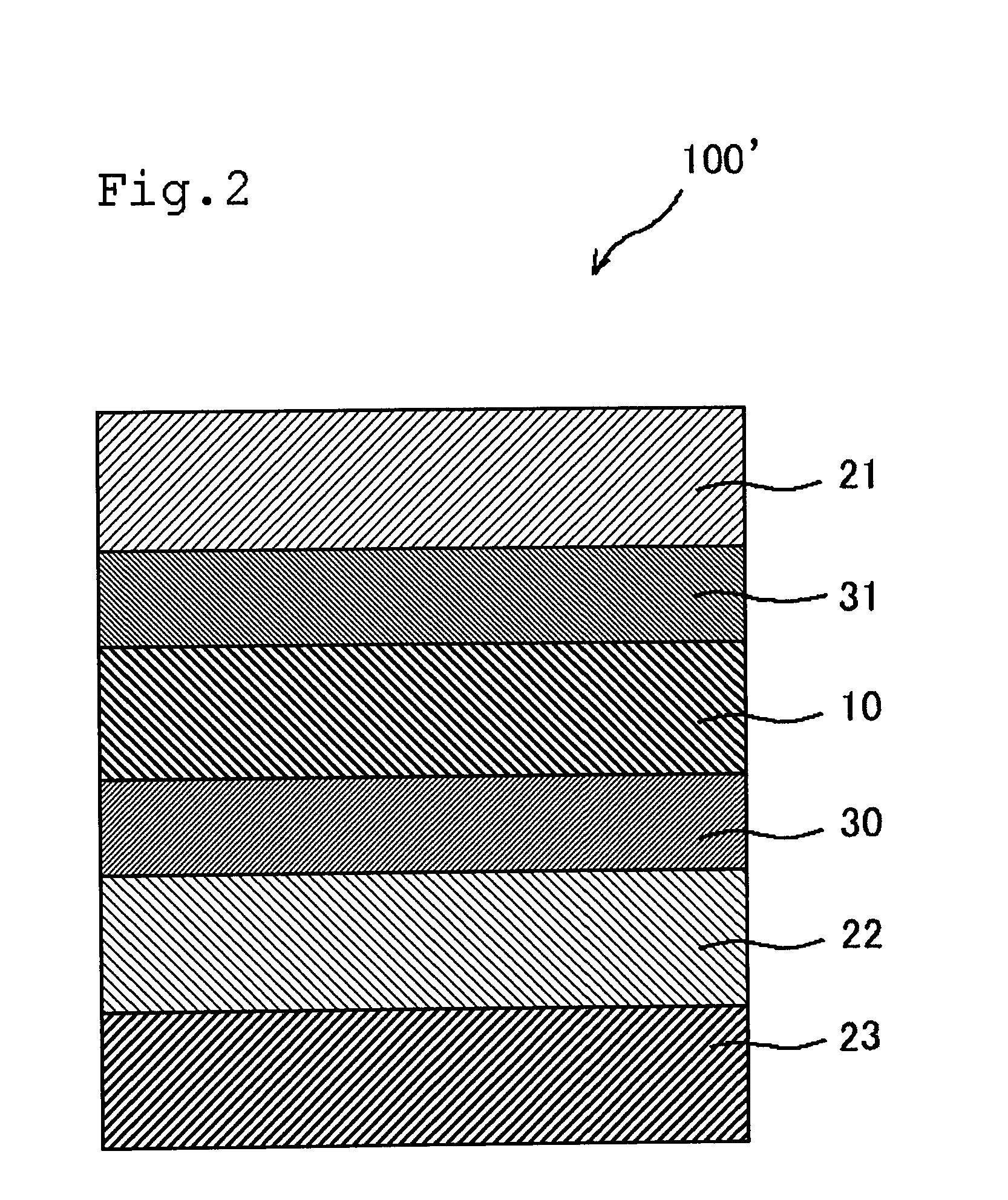
[0022]The liquid crystal display apparatus including the liquid crystal panel of the present invention uses two polarizing plates with a transmittance adjusted and a retardation plate, and further uses a linearly polarized light separation type reflective polarizing plate as a third polarizing plate, thereby exhibiting excellent display properties in which a contrast ratio in a front direction is remarkably higher than that of a liquid crystal display apparatus including a conventional liquid crystal panel.

Problems solved by technology

The LCD has a problem in that a contrast ratio in front and oblique directions is low.
Further, although it is known to enhance the brightness of a liquid crystal display apparatus using a reflective polarizing plate for the purpose of enhancing display properties of the liquid crystal display apparatus, the enhancement of a contrast using the reflective polarizing plate has not been realized.

Method used


Image

  • Liquid crystal panel and liquid crystal display apparatus
  • Liquid crystal panel and liquid crystal display apparatus
  • Liquid crystal panel and liquid crystal display apparatus

Examples


reference example 1

[0190]A polymer film (“VF-PS#7500” (trade name) manufacture by Kuraray Co., Ltd.) with a thickness of 75 μm containing a polyvinyl alcohol-based resin as a main component was soaked in 5 baths under the following conditions [1] to [5] while the tension was being applied to the film in a film longitudinal direction, and stretched so that the final stretching ratio became 6.2 times with respect to the film original length. The stretched film was dried in an air-circulating drying oven at 40° C. for one minute, whereby a polarizer A was produced. A polymer film (“TD80UF” (trade name); Re[590]=0 nm, Rth[590]=60 nm, manufactured by Fujifilm Corporation) with a thickness of 80 μm containing a cellulose-based resin was attached to both sides of the polarizer A via a water-soluble adhesive (GOHSEFIMER Z-200 (trade name) manufactured by Nippon Synthetic Chemical Industry Co., Ltd) containing a polyvinyl alcohol-based resin as a main component, whereby a polarizing plate A was produced. The p...

reference example 2

[0197]A polarizer B and a polarizing plate B were produced by the same conditions and method as those in Reference Example 1, except that the adding amount of iodine in Condition [2] was 0.032 parts by weight with respect to 100 parts by weight of water. The properties of the polarizing plate B are shown in the following Table 1.

reference example 3

[0198]A polarizer C and a polarizing plate C were produced by the same conditions and method as those in Reference Example 1, except that the adding amount of iodine in Condition [2] was 0.031 parts by weight with respect to 100 parts by weight of water. The properties of the polarizing plate C are shown in the following Table 1.


PUM

PropertyMeasurementUnit
transmittanceaaaaaaaaaa

Abstract

The liquid crystal panel according to an embodiment of the present invention includes a liquid crystal cell, a first polarizing plate placed on one side of the liquid crystal cell, a second polarizing plate and a third polarizing plate placed on the other side of the liquid crystal cell in an order starting from a side of the liquid crystal cell, and a retardation plate (A) placed between the liquid crystal cell and the second polarizing plate, wherein a refractive index ellipsoid of the retardation plate (A) has a relationship of nx≧ny>nz, a difference (ΔT2−1=T2−T1) between a transmittance (T2) of the second polarizing plate and a transmittance (T1) of the first polarizing plate is larger than 0%, a difference (ΔT3−2=T3−T2) between a transmittance (T3) of the third polarizing plate and a transmittance (T2) of the second polarizing plate is 4.0% to 7.5%, and the third polarizing plate is a linearly polarized light separation type reflective polarizing plate.

Description

[0001]This application claims priority under 35 U.S.C. Section 119 to Japanese Patent Application Nos. 2008-164000 filed on Jun. 24, 2008, and 2009-143027 filed on Jun. 16, 2009, which are herein incorporated by references.BACKGROUND OF THE INVENTION[0002]1. Field of the Invention[0003]The present invention relates to a liquid crystal panel and a liquid crystal display apparatus having excellent contrast properties.[0004]2. Description of Related Art[0005]A liquid crystal display apparatus (hereinafter, referred to as an LCD) displays characters and images, using the electrooptical characteristics of liquid crystal molecules. The LCD generally uses a liquid crystal panel in which polarizing plates are placed on both sides of a liquid crystal cell, and can display a black image under no voltage application in a normally black mode, for example. The LCD has a problem in that a contrast ratio in front and oblique directions is low. In order to solve this problem, a liquid crystal panel...

Claims


Application Information

Patent Timeline
Patent Type & Authority Applications(United States)
IPC IPC(8): G02F1/1335G02F1/13363
CPCG02F1/133528G02F1/133634G02F1/13363G02F1/133536
Inventor ISHII, TAKAAKIHIGASHI, MASATSUGUMURAKAMI, NAO
Owner NITTO DENKO CORP
Why Eureka
Try Eureka