Magnetic head assembly

a head assembly and magnetic head technology, applied in the direction of maintaining head carrier alignment, special recording techniques, instruments, etc., can solve the problems of slowing down the speed of the increase of recording density, difficult to realize such high recording density, and difficult to efficiently apply high-frequency magnetic field to the medium

Active Publication Date: 2009-12-24
KK TOSHIBA
View PDF78 Cites 35 Cited by
  • Summary
  • Abstract
  • Description
  • Claims
  • Application Information

AI Technical Summary

Problems solved by technology

However, in the 2000s, the problem of thermal fluctuation of the magnetic recording media has been actualized and therefore the speed of the increase of the recording density has temporarily slowed down.
However, it is thought that realization of such high recording density is not easy even by using the perpendicular magnetic recording scheme because the problem of thermal fluctuation is actualized again.
However, in the technique disclosed in the Patent document 1, the high-frequency magnetic field is generated by a coil and therefore it has been difficult to efficiently apply the high-frequency magnetic field to the medium.

Method used


Image

  • Magnetic head assembly
  • Magnetic head assembly
  • Magnetic head assembly

Examples


first embodiment

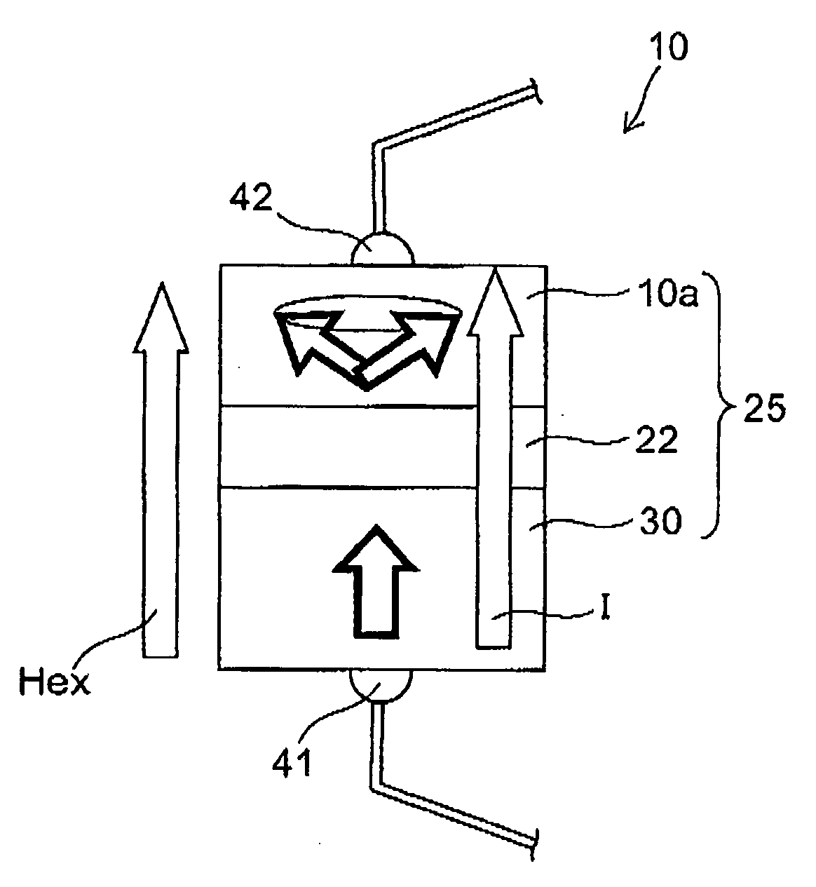
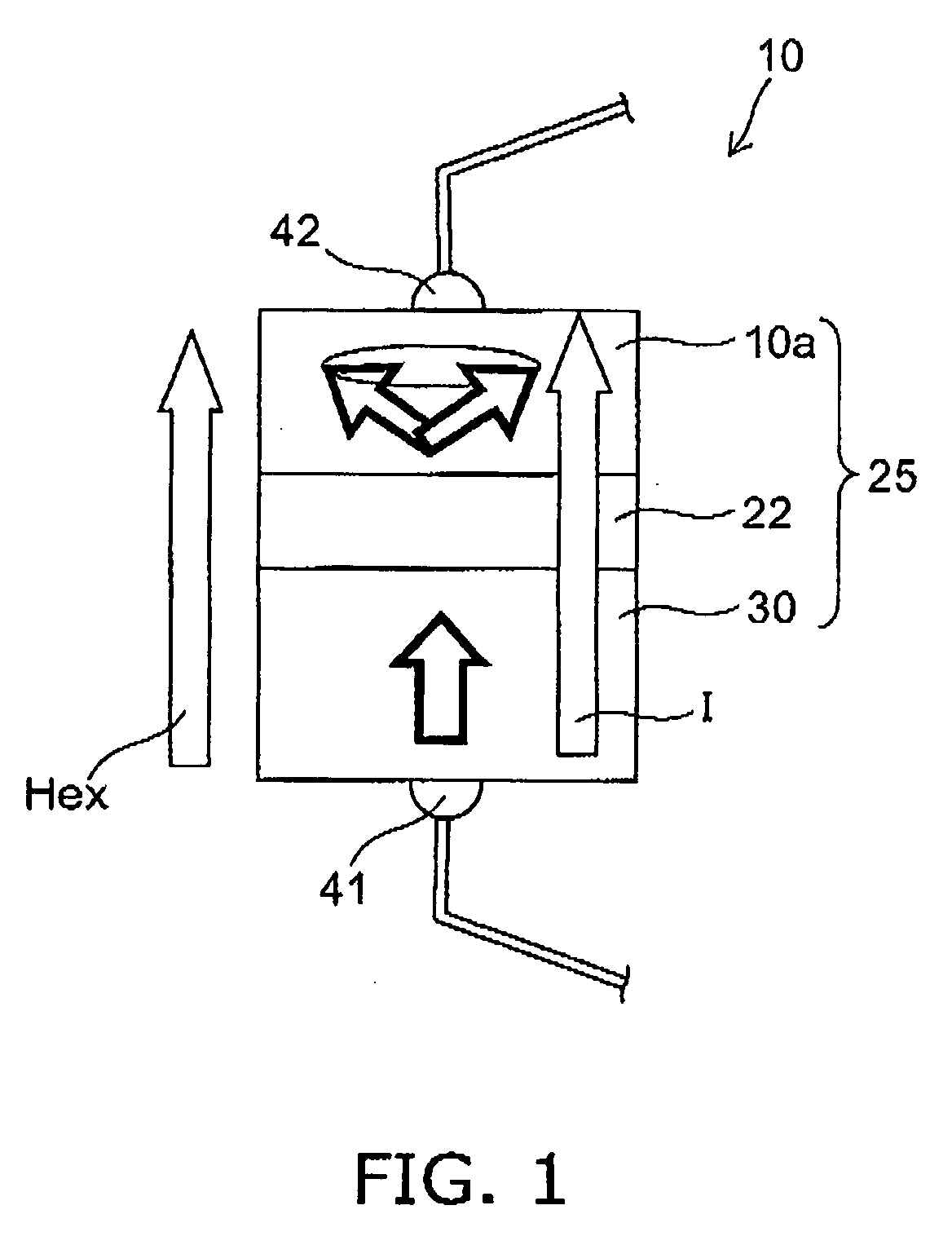
[0034]FIG. 1 is a schematic sectional view illustrating the configuration of a spin torque oscillator according to a first embodiment of the invention.

[0035]As shown in FIG. 1, the spin torque oscillator 10 according to the first embodiment of the invention has a stacked structure 25 having, an oscillation layer (first magnetic body layer) 10a, a spin injection layer (second magnetic body layer) 30, and an intermediate layer 22 provided between the oscillation layer 10a and the spin injection layer 30.

[0036]And, the spin torque oscillator 10 can have one pair of electrodes, namely, a first electrode 41 and a second electrode 42 that can be conducted in the stacked direction of the stacked structure 25. That is, by the first electrode 41 and the second electrode 42, the driving current I is conducted to the stacked structure 25.

[0037]However, at least any one of the first and second electrodes 41 and 42 may be used together with, for example, main magnetic pole and return path (shiel...

second embodiment

[0090]FIG. 6 is a schematic cross-sectional view illustrating the configuration of the spin torque oscillator according to a second embodiment of the invention.

[0091]As shown in FIG. 6, in the spin torque oscillator 10b according to the second embodiment of the invention, as the spin injection layer 30, a stacked film of a (Fe50 at %Co50 at %)76 at %Al24 at % alloy (first spin injection layer 30a) with a layer thickness of 2 nm and a CoPt layer (second spin injection layer 30b) 30b with a layer thickness of 20 nm is used. The first spin injection layer 30a that is a FeCoAl layer is provided at the interface with the intermediate layer 22, namely, on the side of the oscillation layer 10a. In the oscillation layer 10a, a (Fe50 at %Co50 at %)84 at %Al16 at % alloy with a layer thickness of 12 nm is used.

[0092]Other than this, the spin torque oscillator 10b is the same as the spin torque oscillator 10 according to the first embodiment. That is, in the intermediate layer 22, Cu with a la...

third embodiment

[0109]FIG. 8 is a schematic cross-sectional view illustrating the configuration of the spin torque oscillator according to a third embodiment of the invention.

[0110]As shown in FIG. 8, in the spin torque oscillator 10c according to the third embodiment of the invention, as the spin injection layer 30, a stacked film of the FeCoAl layer of the intermediate layer side (first spin injection layer 30a) and the CoPt layer (second spin injection layer 30b) 30b with a layer thickness of 20 nm is used. In the spin torque oscillator according to this embodiment, the oscillation layer 10a does not include a FeCoAl alloy.

[0111]That is, the spin injection layer 30 is composed of a stacked structure of the FeCoAl alloy layer and the CoPt alloy layer that is magnetized and oriented in the perpendicular direction to the film surface, and at the interface with the intermediate layer 22, the FeCoAl alloy layer is disposed. That is, the spin injection layer 30 has a second spin injection layer 30b in...


PUM

PropertyMeasurementUnit
thicknessaaaaaaaaaa
thicknessaaaaaaaaaa
thicknessaaaaaaaaaa

Abstract

A magnetic head assembly includes: a magnetic recording head, a head slider, a suspension and an actuator arm. The magnetic recording head includes a spin torque oscillator and a main magnetic pole. The spin torque oscillator includes, a first magnetic layer including at least one selected from the group consisting of a Fe—Co—Al alloy, a Fe—Co—Si alloy, a Fe—Co—Ge alloy, a Fe—Co—Mn alloy a Fe—Co—Cr alloy and a Fe—Co—B alloy, a second magnetic layer, and an intermediate layer provided between the first magnetic layer and the second magnetic layer. The main magnetic pole is placed together with the spin torque oscillator. The magnetic recording head is mounted on the head slider. The head slider is mounted on one end of the suspension. The actuator arm is connected to other end of the suspension.

Description

CROSS-REFERENCE TO RELATED APPLICATIONS[0001]This application is based upon and claims the benefit of priority from the prior Japanese Patent Application No. 2008-161025, filed on Jun. 19, 2008; the entire contents of which are incorporated herein by reference.BACKGROUND OF THE INVENTION[0002]This invention relates to a magnetic head assembly.Background Art[0003]In the 1990s, practical application of MR (Magneto-Resistive effect) head and GMR (Giant Magneto-Resistive effect) head has acted as a trigger and recording density and recording capacity of HDD (Hard Disk Drive) have drastically increased. However, in the 2000s, the problem of thermal fluctuation of the magnetic recording media has been actualized and therefore the speed of the increase of the recording density has temporarily slowed down. Even so, it has played a leading role that perpendicular magnetic recording, which is fundamentally more advantageous than the longitudinal magnetic recording in high-density recording, h...

Claims


Application Information

Patent Timeline
Patent Type & Authority Applications(United States)
IPC IPC(8): G11B5/60
CPCG11B5/3146H03B15/006Y10T428/1143G11B5/02Y10T428/115G11B2005/0005G11B2005/0024G11B5/314Y10T428/1121Y10T428/1171
Inventor YAMADA, KENICHIROIWASAKI, HITOSHITAKAGISHI, MASAYUKIFUNAYAMA, TOMOMI
Owner KK TOSHIBA
Why Eureka
Try Eureka