Power supply having maximum power point tracking function

a technology of power supply and maximum power point, applied in the direction of electric variable regulation, process and machine control, instruments, etc., can solve the problems of low generation efficiency, increased manufacturing costs, and increased circuit siz

Inactive Publication Date: 2009-12-24
SAMSUNG ELECTRO MECHANICS CO LTD
View PDF7 Cites 18 Cited by
  • Summary
  • Abstract
  • Description
  • Claims
  • Application Information

AI Technical Summary

Problems solved by technology

Though these solar photovoltaic power generators have attracted attention as new alternative energy supplies, they have low generation efficiency.
However, in order that the operating point tracks the maximum power point, an expensive control device, such as a micro controller, is required, and a complicated peripheral circuit is further required for the control device, which causes an increase in manufacturing costs, and an increase in circuit size.

Method used


Image

  • Power supply having maximum power point tracking function
  • Power supply having maximum power point tracking function
  • Power supply having maximum power point tracking function

Examples


Embodiment Construction

[0027]Exemplary embodiments of the present invention will now be described in detail with reference to the accompanying drawings.

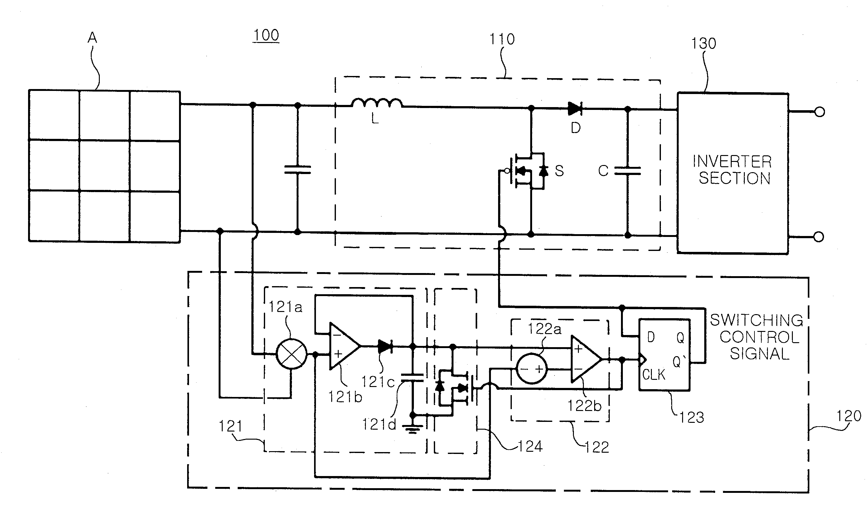
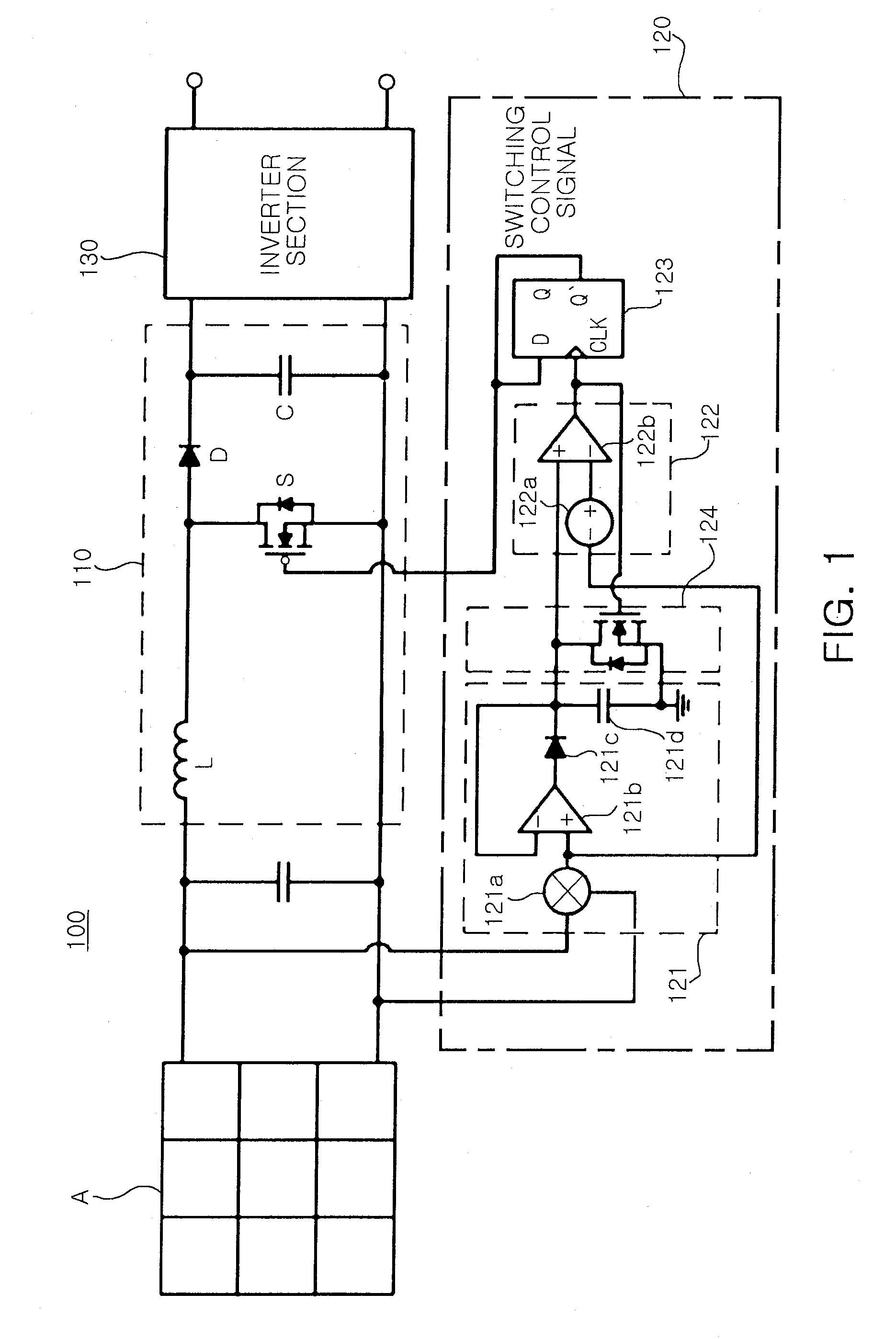
[0028]FIG. 1 is a configuration view illustrating a power supply according to an exemplary embodiment of the invention.

[0029]Referring to FIG. 1, a power supply 100 according to an exemplary embodiment of the invention includes a converter section 110 and a maximum power point tracking section 120.

[0030]The converter section 110 switches input power and converts the switched input power into DC power having a predetermined voltage level. The input power may be supplied from a solar array A. The power supply 100 may be a solar photovoltaic generator that generates power using sunlight.

[0031]The converter section 110 may include an inductor L, a switch S, a diode D, and a capacitor C.

[0032]The inductor L boosts a voltage level of the power from the solar array A. The switch S switches the power whose voltage level is inverted by the inductor L according to a...


PUM


Abstract

The present invention relates to power supplies, and more particularly, to a power supply having a maximum power point tracking function that controls power switching so that a detected power value is within a reference range having a maximum power point in a predetermined current-voltage curve. A power supply having a maximum power point tracking function according to an aspect of the invention includes: a converter section switching input power and converting the switched input power into predetermined DC power; and a maximum power point tracking section detecting a power value determined according to a switching operation of the converter section among power values included in a predetermined power-voltage curve, and controlling the switching operation of the converter section so that the detected power value is located within a predetermined reference range having a maximum power value among the power values included in the power-voltage curve.

Description

CROSS-REFERENCE TO RELATED APPLICATIONS[0001]This application claims the priority of Korean Patent Application No. 2008-0059456 filed on Jun. 24, 2008, in the Korean Intellectual Property Office, the disclosure of which is incorporated herein by reference.BACKGROUND OF THE INVENTION[0002]1. Field of the Invention[0003]The present invention relates to power supplies, and more particularly, to a power supply having a maximum power point tracking function that controls power switching so that a detected power value is within a reference range having a maximum power point in a predetermined current-voltage curve.[0004]2. Description of the Related Art[0005]In general, power supplies that supply driving power to home equipment and industrial equipment are necessarily used to drive the equipment.[0006]Recently, among the power supplies, solar photovoltaic power generators have received much attention as new alternative power supplies since they use infinite energy sources that are environ...

Claims


Application Information

Patent Timeline
Patent Type & Authority Applications(United States)
IPC IPC(8): H02M7/42
CPCG05F1/67Y02E10/56H02J3/38H02J7/35
Inventor KIM, JIN WOOKHONG, SUNG SOOROH, CHUNG WOOKHAN, SANG KYOOKIM, JONG SUNWON, JAE SUNOH, DONG SEONGJANG, DEA MINKIM, JONG HAE
Owner SAMSUNG ELECTRO MECHANICS CO LTD
Why Eureka
Try Eureka