Eureka AIR delivers breakthrough ideas for toughest innovation challenges, trusted by R&D personnel around the world.

Methods and systems for analyzing t-wave alternants

a technology of alternant and t-wave, applied in the field of implantable cardiac devices, can solve the problems of increasing instability and resulting cardiac arrhythmias, inconvenient and cumbersome difficulty in providing continuous and regular t-wave alternant pattern monitoring, so as to reduce the number of atp attempts, improve antiarrhythmia therapy, and high complexity

Inactive Publication Date: 2009-12-24
PACESETTER INC
View PDF1 Cites 18 Cited by
  • Summary
  • Abstract
  • Description
  • Claims
  • Application Information

AI Technical Summary

Benefits of technology

[0017]In accordance with one embodiment of the invention an approach to prospectively predict the complexity of arrhythmias based on beat by beat alterations before the actual arrhythmia onset is provided. This method provides an early prediction of an arrhythmia and allows for optimizing antiarrhythmia therapy. In this embodiment, the method is used in implantable devices to predict the complexity of coming VT / VF based on beat by beat alterations before the actual onset of VT / VF. The method extracts EGM features and tracks beat by beat alterations. These features may include the amplitude, duration, slope, area under the curve of QRS complex and T wave portion, as well as conduction velocity. Table 1. illustrates some features that can be extracted from ventricular IEGM. Based on the degree of alterations, the method predicts the complexity of VT / VF and selects optimal therapy. For example, reduce the number of ATP attempts when the method predicts high complexity.

Problems solved by technology

Further, the alternating repolarization pattern can lead to increased instability and consequent cardiac arrhythmias.
Unfortunately, the above detection method requires the use of medical equipment that must be operated by medical personnel in a medical facility such as a physician's office.
As a result, T-wave alternan pattern monitoring has been inconvenient and cumbersome.
As a result, it is difficult to provide continuous and regular T-wave alternan pattern monitoring.
However, the prior art detection method does not lend itself for such application due to, for example, the required long term monitoring, surface ECG, and robust computational requirements for Fourier series transformation.
However, the relationship between the degree of beat by beat alterations prior to VT / VF and the complexity of VT / VF has not been known.
However, these equations cannot be directly applied to IEGM signal analysis because of the morphological difference between the two signals caused by recording location as well as the fact that IEGM signals are attenuated by the internal filter in the device.

Method used


Image

  • Methods and systems for analyzing t-wave alternants
  • Methods and systems for analyzing t-wave alternants
  • Methods and systems for analyzing t-wave alternants

Examples


Embodiment Construction

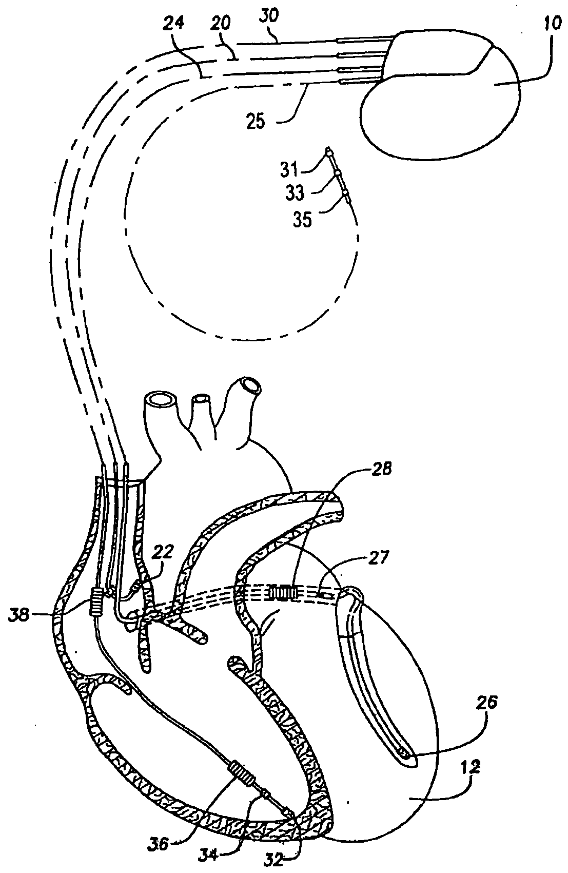
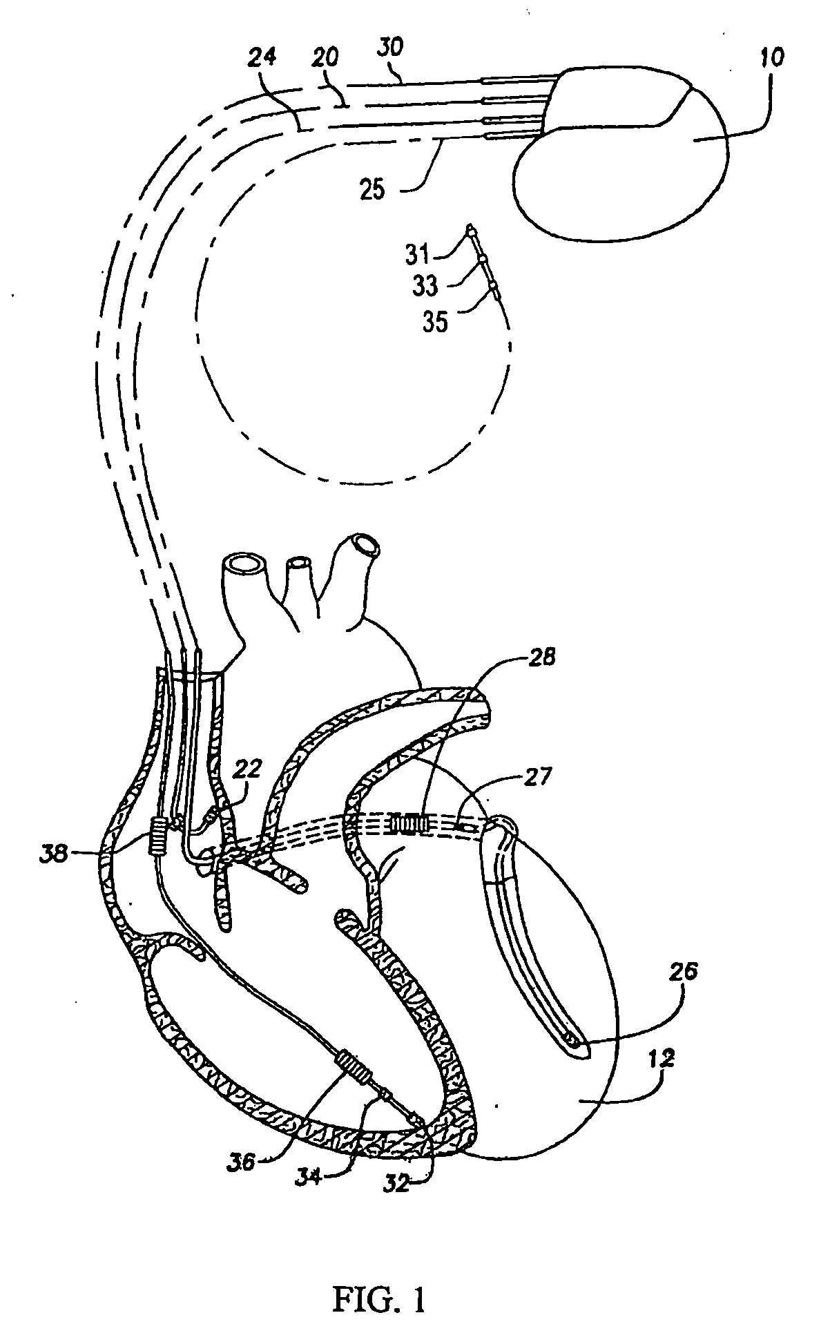
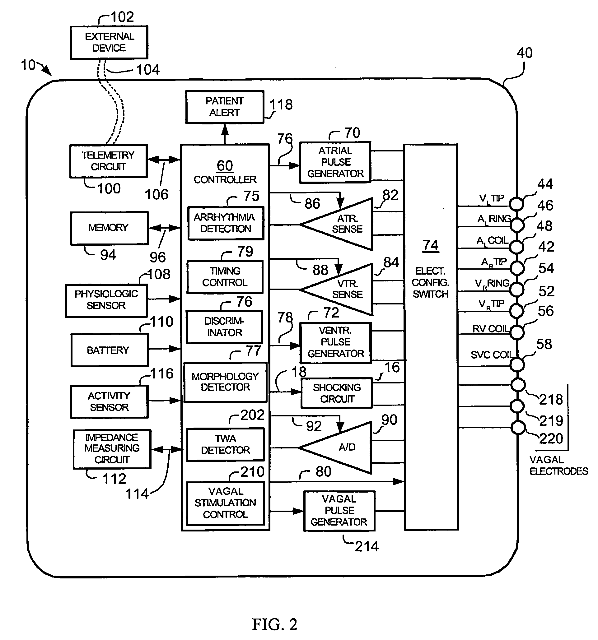
[0035]The following detailed description of the present invention refers to the accompanying drawings that illustrate exemplary embodiments consistent with this invention. Other embodiments are possible, and modifications may be made to the embodiments within the spirit and scope of the present invention. Therefore, the following detailed description is not meant to limit the invention. Rather, the scope of the invention is defined by the appended claims.

[0036]It would be apparent to one of skill in the art that the present invention, as described below, may be implemented in many different embodiments of hardware, software, firmware, and / or the entities illustrated in the figures. Any actual software and / or hardware described herein is not limiting of the present invention. Thus, the operation and behavior of the present invention will be described with the understanding that modifications and variations of the embodiments are possible, given the level of detail presented herein.

Ex...


PUM


Abstract

Embodiments of the present invention relate to implantable systems, and methods for use therein, that can detect T-wave alternans and analyze the detected alternans to provide information regarding cardiac instabilities and predict impending arrhythmias.

Description

PRIORITY / INCORPORATION BY REFERENCE [0001]The present application claims priority to provisional U.S. Patent Application No. 61 / 073,666, entitled “Methods and Systems for Analyzing T-Wave Alternans” filed on Jun. 18, 2008, the specification of which is expressly incorporated herein by reference in its entirety.CROSS REFERENCE TO RELATED APPLICATIONS[0002]The present invention relates to the following commonly assigned patents and applications, each of which is incorporated herein by reference: U.S. Pat. No. 7,027,867, granted Apr. 11, 2006, entitled “Implantable Cardiac Device Having a System for Detecting T-Wave Alternan Patterns and Method,” U.S. Pat. No. 7,245,968, entitled “Implantable Cardiac Device Providing Rapid Pacing T-wave Alternan Pattern Detection and Method,” granted Jul. 17, 2007; U.S. patent application Ser. No.11 / 229,411, entitled “Methods and Systems for Detecting the Presence of T-Wave Alternans,” filed Sep. 16, 2005; and U.S. patent application Ser. No. 11 / 229,41...

Claims


Application Information

Patent Timeline
IPC IPC(8): A61B5/0452A61B5/366A61B5/352
CPCA61B5/0452A61B5/0472A61B5/0456A61N1/37A61B5/349A61B5/366A61B5/352A61B5/355
Inventor QU, FUJIANSHAH, RIDDHI
Owner PACESETTER INC
Why Eureka
Eureka Blog
Learn More