Light diffuser and process for producing the same

a technology of diffuser and light, applied in the field of light diffuser, can solve the problems of relatively elaborate methods, high production cost, and high risk of infection, and achieve the effect of significantly reducing the risk of metastatic tumorous cells

Active Publication Date: 2009-12-24
WOODWELDING
View PDF16 Cites 73 Cited by
  • Summary
  • Abstract
  • Description
  • Claims
  • Application Information

AI Technical Summary

Benefits of technology

[0009]The object of the invention is to create a light diffuser as well as a method for producing the same. The light diffuser according to the invention is to be suitable for most diverse applications, not only medical but also technical applications, in particular however for the aforementioned introduction of diffuse light into bone tissue (photodynamic therapy) and for the homogenous illumination of hollow biological structures (hollow organs). Compared to the production of known light diffusers, the method for producing the light diffuser according to the invention is to be simpler and it is to enable a simple adjustment to given circumstances, of the geometry of the space to be provided with diffuse light.
[0017]The properties of an artificial porous shaping material suitable for producing the diffuser according to the invention can be such that it can be removed from the diffuser produced therein e.g. by dissolution in an appropriate solvent, by etching, by melting or subliming. Providing that the shaping material has at least locally suitable properties, it can also remain on the diffuser surface and form a kind of diffuser cap, which, due to its porosity, can e.g. further scatter light deflected by the diffuser. Such a diffuser cap of the porous shaping material may already have the shape of a cap, i.e. relatively thin walls, when the diffuser is produced, or it may be appropriately processed afterwards. The diffuser cap can also be fashioned for a specific non-optical additional function or can be shaped appropriately by a subsequent addition or removal of material or by re-forming. The porosity of the shaping material can be homogenous. In particular if the diffuser cap has specific non-optical additional functions, it may be advantageous to fashion the porosity inhomogeneous and to vary it depending on the function of each part of the diffuser cap. Thus a diffuser cap can be porous where it is to be interpenetrated by a diffuser material while the exterior surface of the cap is smooth and free from pores in order to minimize friction in the tissue and contamination e.g. in the endoscopic application.
[0018]Diffusers according to the invention, produced by means of an artificial shaping material, suit non-medical and medical applications, but in particular the introduction of diffuse light in soft tissue or in tissue voids (e.g. blood vessels, respiratory passages or digestive tract). In that case, the same procedure is followed for the introduction of the diffuse light as with diffusers according to the state of the art, wherein the diffuser according to the invention is coupled with a light conductor or a light source and is positioned for the application. Then light of a desired wavelength is coupled from the light conductor into the diffuser, which scatters the light and, thus, brings it into the tissue. A particular advantage of flexible diffusers produced by the above mentioned method is the fact that due to its flexibility, the diffuser can be bent by the operator using per se known catheter techniques around a large solid angle, such enabling a corresponding control of the instrument on one hand and a targeted illumination on the other.
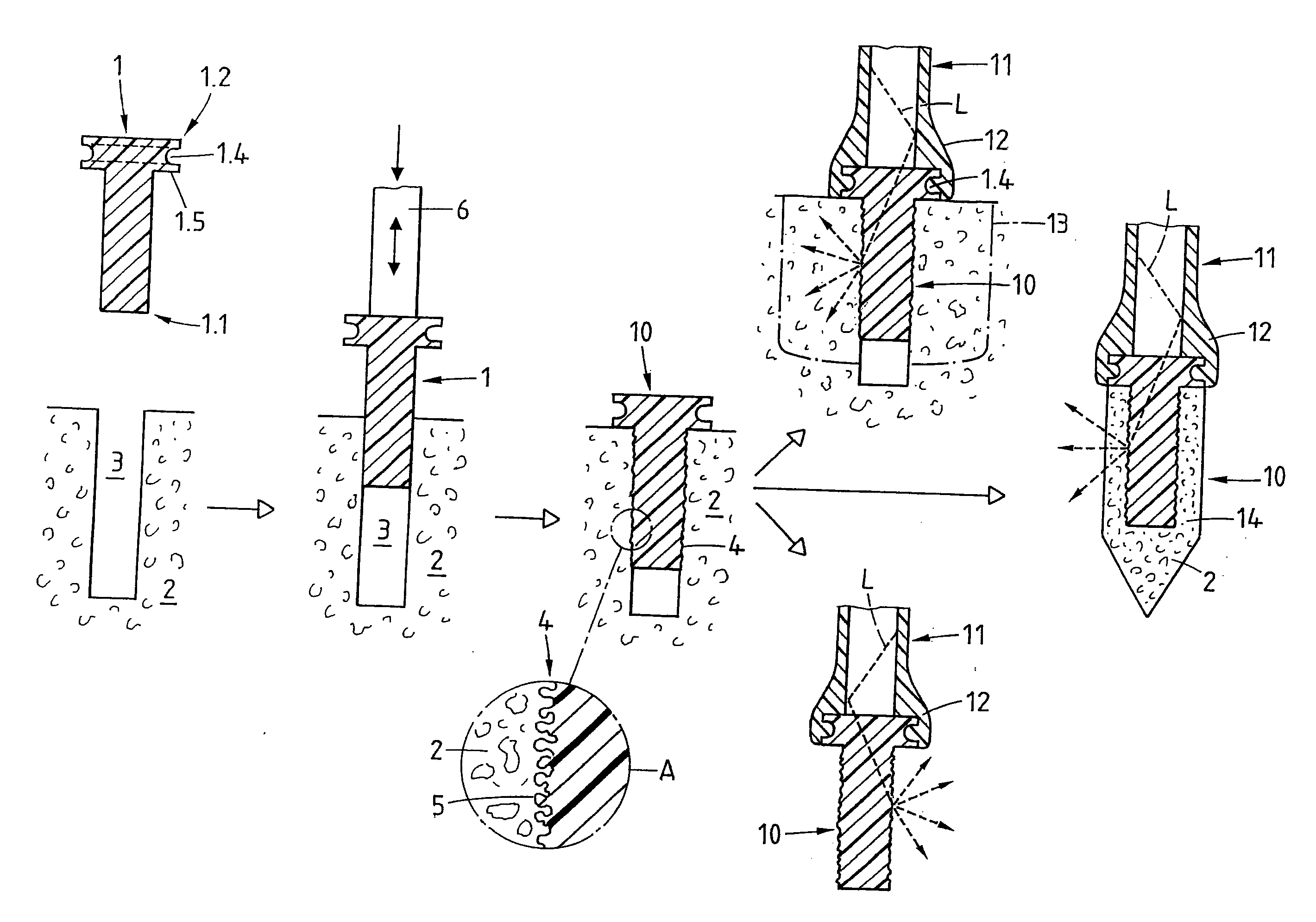
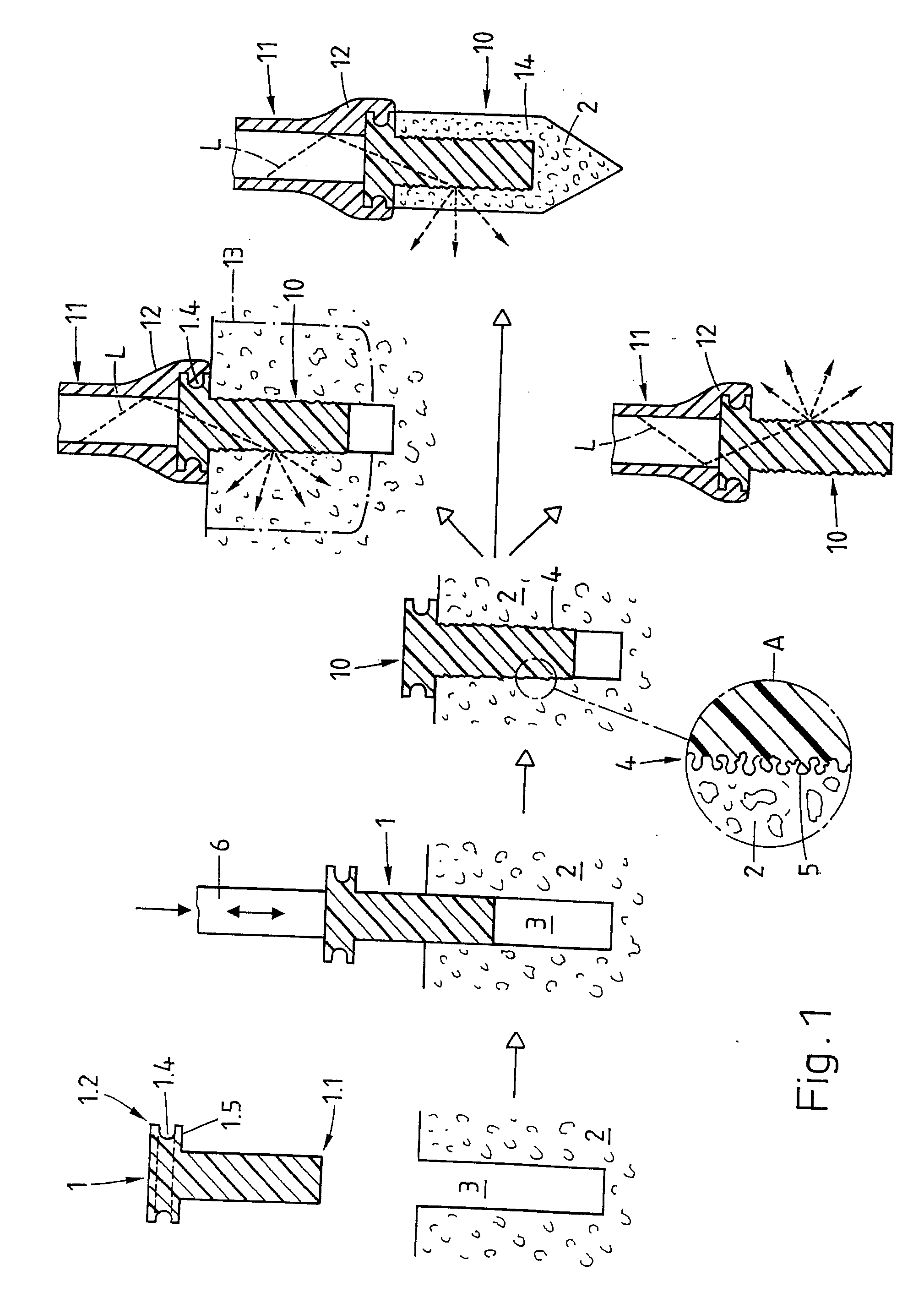
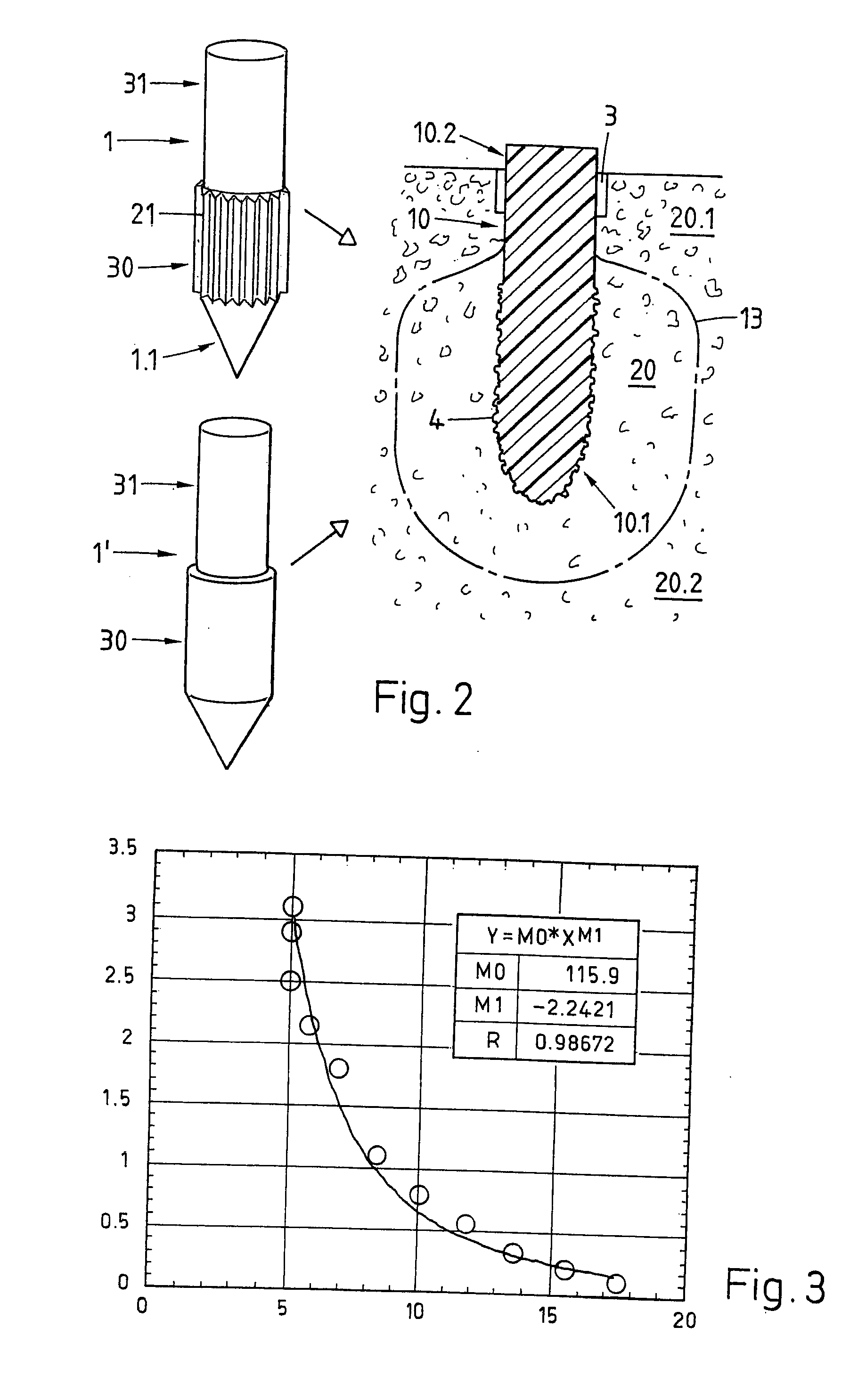
[0020]The use of viable tissue, in particular of bone tissue, as porous shaping material for producing the diffuser from a diffuser blank means that the diffuser blank is implanted and the light scattering surface structures develop during implantation (in situ). It is not imperative to create an opening (e.g. a bore) in the osseous material prior to the implantation. E.g. the cortical layer of a bone can be drilled in advance and the implant positioned in the bore before it is driven by pressure force and simultaneous vibration into the spongiosa, without drilling the latter. With such a diffuser produced in situ, a tumour (or metastasis) located in the spongiosa can be illuminated in the simplest way. The diffuser implant can remain in the bone tissue for further illuminations, where with its intensive anchoring it may represent a welcome further reinforcement of the osseous tissue debilitated by the tumour. The diffuser implant can also consist of a biologically resorbable light conducting material so that it does not need to be removed after its use for the illumination of the tissue and is gradually replaced by regenerated bone tissue.
[0022]The crucial advantage of the diffuser produced by implantation in viable bone tissue over known diffusers used for the same purpose, is the fact that precursory drilling is not necessarily needed and that the implant does not necessarily need to be removed, or to be removed immediately after the application of the diffuser for an illumination or activation. This means that no element needs to be removed from the tissue to be treated before or immediately after the treatment and therefore the danger of spreading diseased cells, e.g. metastasizing tumorous cells is considerably reduced.

Problems solved by technology

The known diffusers described above are manufactured by relatively elaborate methods and are therefore expensive.
They nevertheless have to be treated as disposable items as they are difficult to clean and sterilize and the risk of infection is clinically often considered too high for a repeated application.

Method used


Image

  • Light diffuser and process for producing the same
  • Light diffuser and process for producing the same
  • Light diffuser and process for producing the same

Examples


Embodiment Construction

[0032]FIG. 1 illustrates the method according to the invention for producing a light diffuser with the aid of a sequence of sections through the diffuser during production. It shows the production of an exemplary light diffuser, which is to have a more-or-less cylindrical active range. As described above, the diffuser can be produced in situ in a bone, or ex situ by means of an artificial shaping material, which is interpenetrated by the diffuser material in a contact layer, wherein for using the diffuser, the shaping material may be left as a diffuser cap on the diffuser or is removed therefrom.

[0033]The diffuser blank 1 consisting of a suitably transparent thermoplastic material (in a solid state) has e.g. an essentially cylindrical form with a distal end 1.1 and a proximal end 1.2, wherein the proximal end 1.2 is furnished with a means to couple an appropriately primed distal light conductor end 11, e.g. with a circumferential groove 1.4.

[0034]In the illustrated example, essentia...


PUM

PropertyMeasurementUnit
pore sizeaaaaaaaaaa
pore sizeaaaaaaaaaa
lengthaaaaaaaaaa

Abstract

A light diffuser (10), which is particularly suitable for introducing diffuse light into a tissue, is produced by interpenetration of a diffuser material in a liquid state into a boundary layer (4) of a porous shaping material, by which process a diffuser surface is formed having a surface structure which represents essentially a negative of the pore structure of the shaping material and includes undercut structures induced by a surface tension. The light diffuser (10) is e.g. produced by introducing a diffuser blank (1) including material which is liquefiable through mechanical vibration into the shaping material and simultaneously stimulating it with mechanical vibrations, such that the liquefiable material liquefies at least there where it is in contact with the shaping material and is pressed into the shaping material. An in situ production of the diffuser is particularly advantageous for photodynamic therapy in bone tissue (20).

Description

BACKGROUND OF THE INVENTION[0001]1. Field of the Invention[0002]The invention concerns a light diffuser according to the generic term of the first independent claim, as well as a method for producing the light diffuser according to the generic term of the corresponding independent claim. The light diffuser according to the invention is suitable for the diffuse deflection of light delivered to the diffuser from a light source or through a light conductor in an essentially axial direction. The light diffuser according to the invention is e.g. suitable for application in endoscopic methods, e.g. for the targeted introduction of diffuse light into tissue structures, in particular into bone tissue, and for the consistent illumunation of hollow biological structures.[0003]2. Description of Related Art[0004]Diffuse light is applied in tissue structures e.g. in the so-called photodynamic therapy methods known in particular for the treatment of tumorigenic diseases. For this purpose a substa...

Claims


Application Information

Patent Timeline
Patent Type & Authority Applications(United States)
IPC IPC(8): A61B18/18
CPCA61B2018/2261A61B18/20
Inventor MAYER, JORGAESCHLIMANN, MARCELTORRIANI, LAURENTWALT, HEINRICH
Owner WOODWELDING
Why Eureka
Try Eureka