Seismic vibrator

a vibrator and seismic source technology, applied in the field of geological exploration, can solve the problems of not being able to use the same frequency range of vibrators, the limited power that such sources known to the art can generate, and sources that have never been commercially deployed

a vibrator and seismic source technology, applied in the field of geological exploration, can solve the problems of not being able to use the same frequency range of vibrators, the limited power that such sources known to the art can generate, and sources that have never been commercially deployed

US20090321175A1Inactive Publication Date: 2009-12-31PGS GEOPHYSICAL AS

Image

  • Seismic vibrator
  • Seismic vibrator
  • Seismic vibrator

Examples


Embodiment Construction

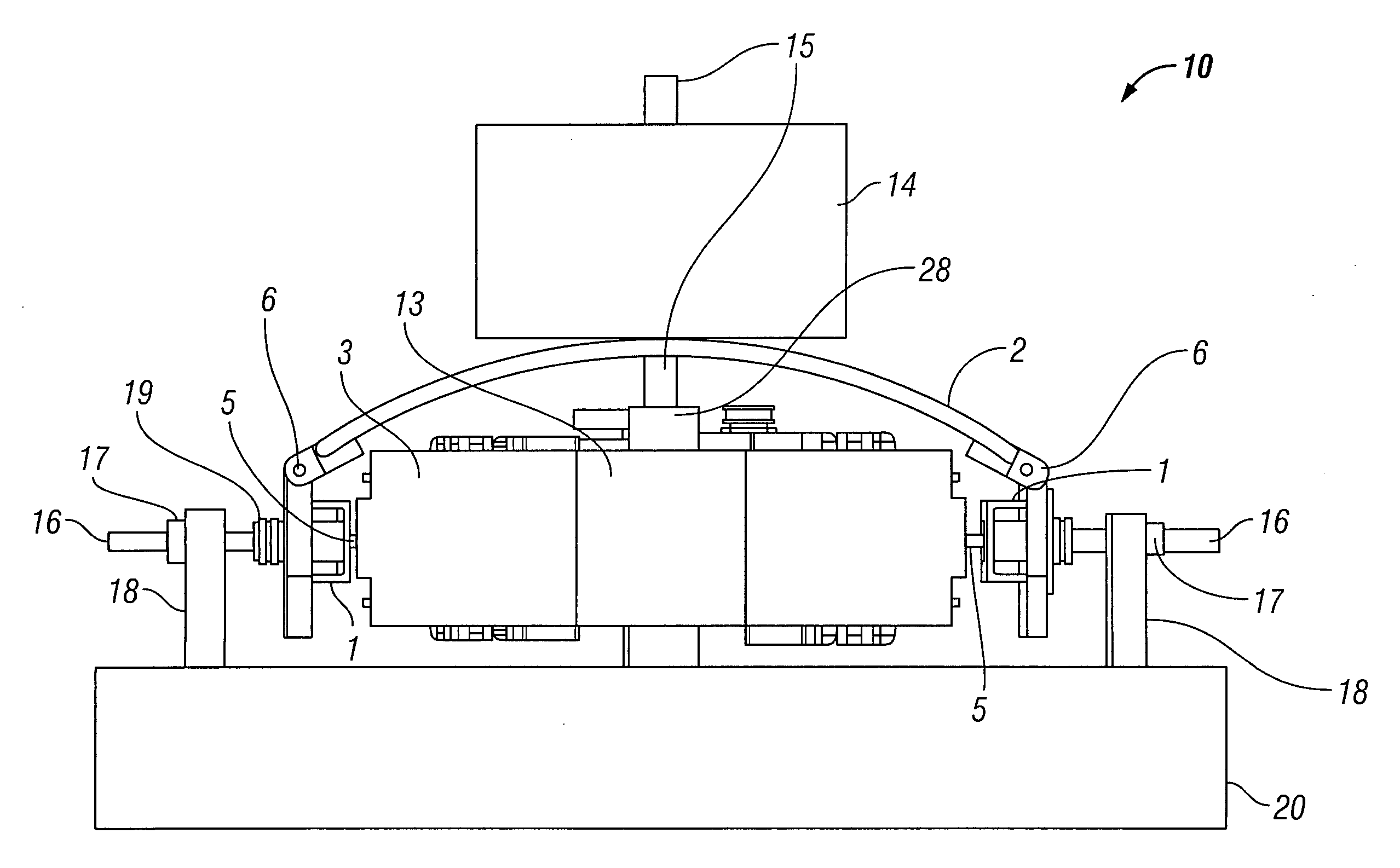
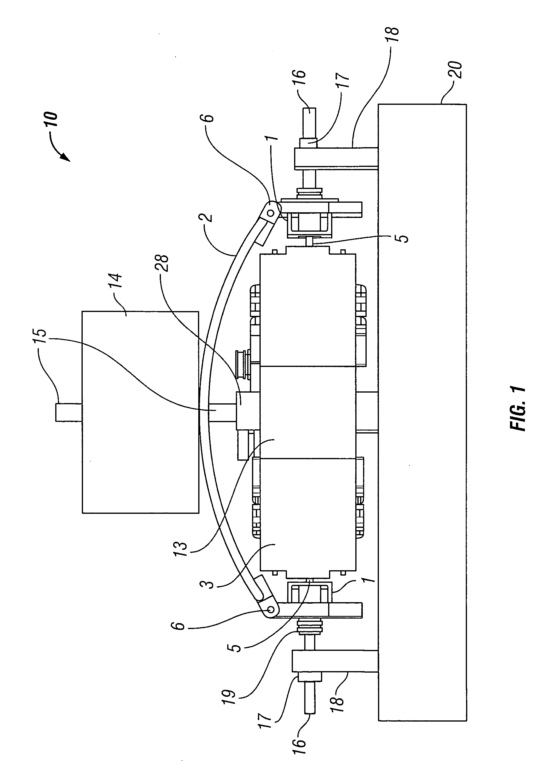
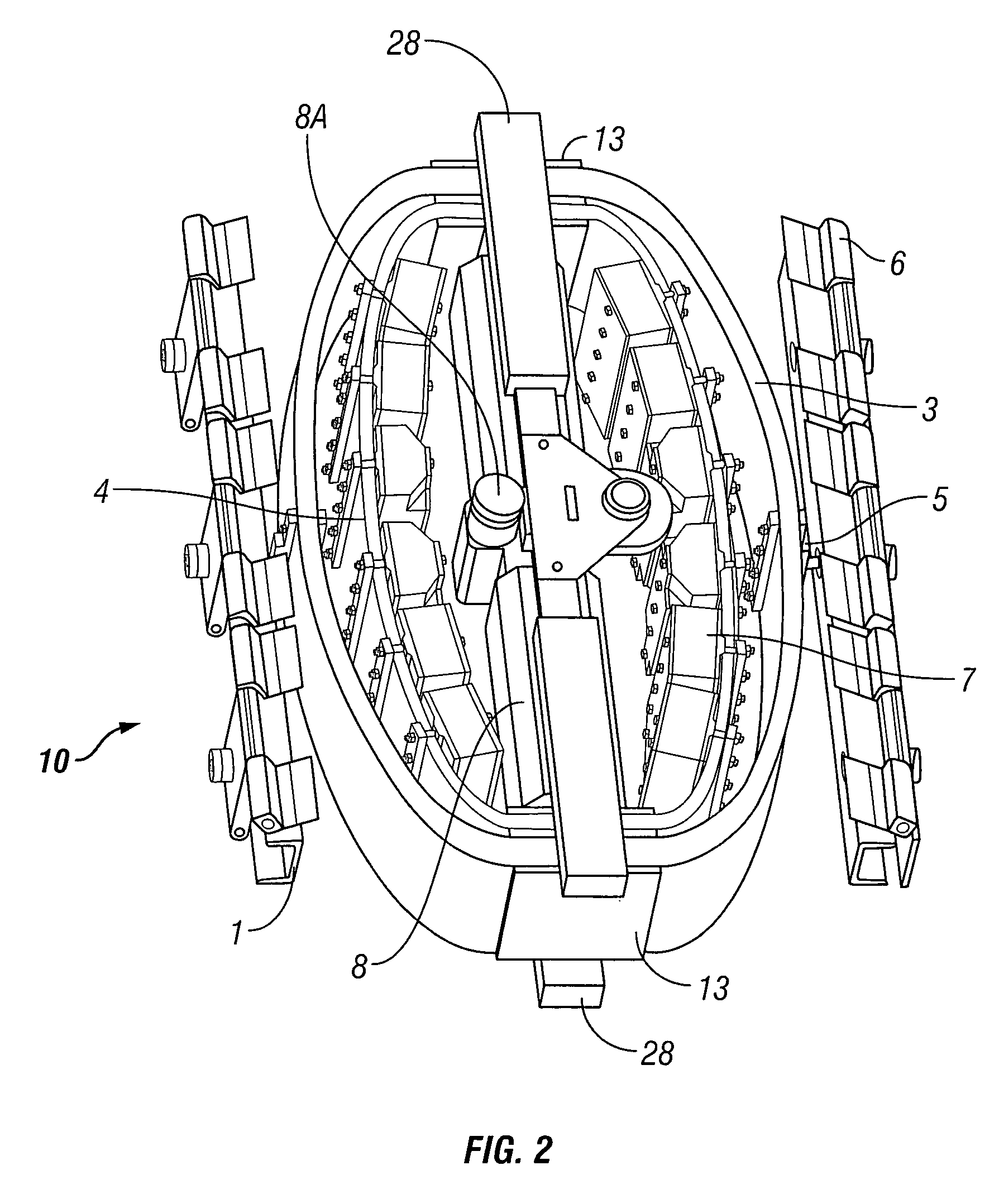
[0019]The description of the invention that follows will begin with a brief explanation of the frequency response of a seismic vibrator in contact with the Earth. Following that is a description of an example vibrator.

[0020]The total impedance that will be experienced by a seismic vibrator may be expressed as follows:

Zr=Rr+jXr  (Eq. 1)

[0021]where Zr is the total impedance;

[0022]Rr is the radiation impedance, and

[0023]Xr is the reactive impedance.

[0024]In an analysis of the energy transfer to the Earth from a seismic vibrator, the system of the vibrator and the Earth may be approximated as a baffled piston. In the expression of the total impedance that will be experienced, the radiation impedance Rr of a baffled piston is provided by the expression:

Rr=πa2ρ0cR1(x)  (Eq. 2)

[0025]and the reactive impedance is:

Xr=πa2ρ0cX1(x)(Eq.3)wherex=2ka=4πaλ=2ωac(Eq.4)R1(x)=1-2xJ1(x)and(Eq.5)X1(x)=4π∫0π2sin(xcosα)sin2αα(Eq.6)

In the above expressions ρ0=density of the Earth (ground), ω=angular frequen...


PUM


Abstract

A seismic vibrator includes a transducer, a reactive mass, a base plate to couple motion of the reactive mass to subsurface formations and a linkage system configured to couple motion of the transducer to the reactive mass and the base plate. The linkage system cooperates with the reactive mass and the transducer to define a first resonant frequency and a second resonant frequency within a range of 1 to 300 Hz.

Description

CROSS-REFERENCE TO RELATED APPLICATIONS[0001]Not applicable.STATEMENT REGARDING FEDERALLY SPONSORED RESEARCH OR DEVELOPMENT[0002]Not applicable.BACKGROUND OF THE INVENTION[0003]1. Field of the Invention[0004]This invention relates generally to geophysical exploration and in particular to a vibratory seismic source useful in geophysical exploration. More particularly, the invention relates to a vibrator using a magnetostrictive driver.[0005]2. Background Art[0006]Seismic energy sources, including vibrators, are used in geophysical exploration on land and in water covered areas of the Earth. Acoustic energy generated by such sources travels downwardly into the Earth, is reflected from reflecting interfaces in the subsurface and is detected by seismic receivers, typically hydrophones or geophones, on or near the Earth's surface or water surface.[0007]Most of the sources used today in land-based seismic survey operations are hydraulically actuated vibrators. Other examples of seismic en...

Claims


Application Information

Patent Timeline
31 Dec 2009
Publication
US20090321175A1
IPC
G01V1/04
CPC
G10K9/121; G01V1/145
Inventors
TENGHAMN, STIG RUNE LENNART