Transition piece mounting bracket and related method

Active Publication Date: 2009-12-31
GENERAL ELECTRIC CO
View PDF16 Cites 11 Cited by
  • Summary
  • Abstract
  • Description
  • Claims
  • Application Information

AI Technical Summary

Benefits of technology

[0003]This invention provides a two-piece forward transition piece mounting bracket assembly wherein one piece of the bracket assembly can be used for a shorter life cycle interval but, when it is desired to extend service life, the second piece of the bracket may

Problems solved by technology

The mounting bracket generally requires replacement after completion of a specified number of hours in operation

Method used


Image

  • Transition piece mounting bracket and related method
  • Transition piece mounting bracket and related method
  • Transition piece mounting bracket and related method

Examples


Example

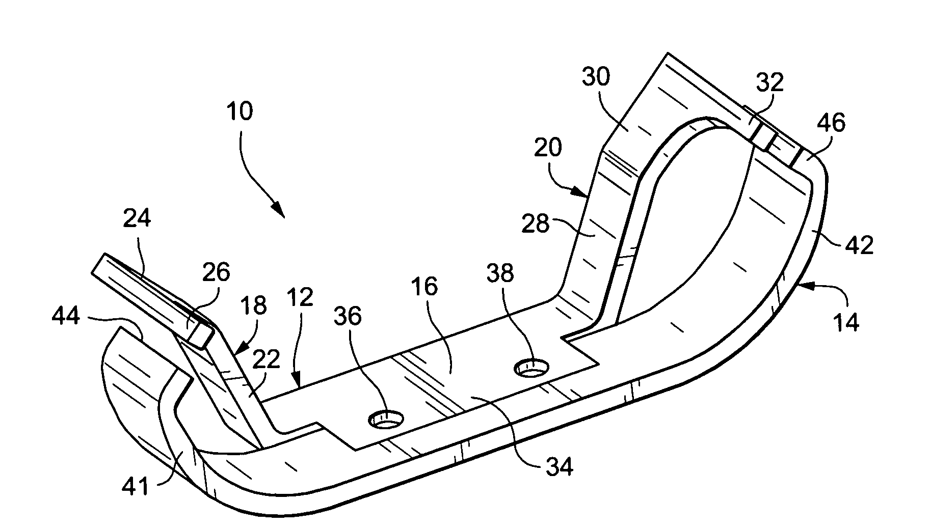
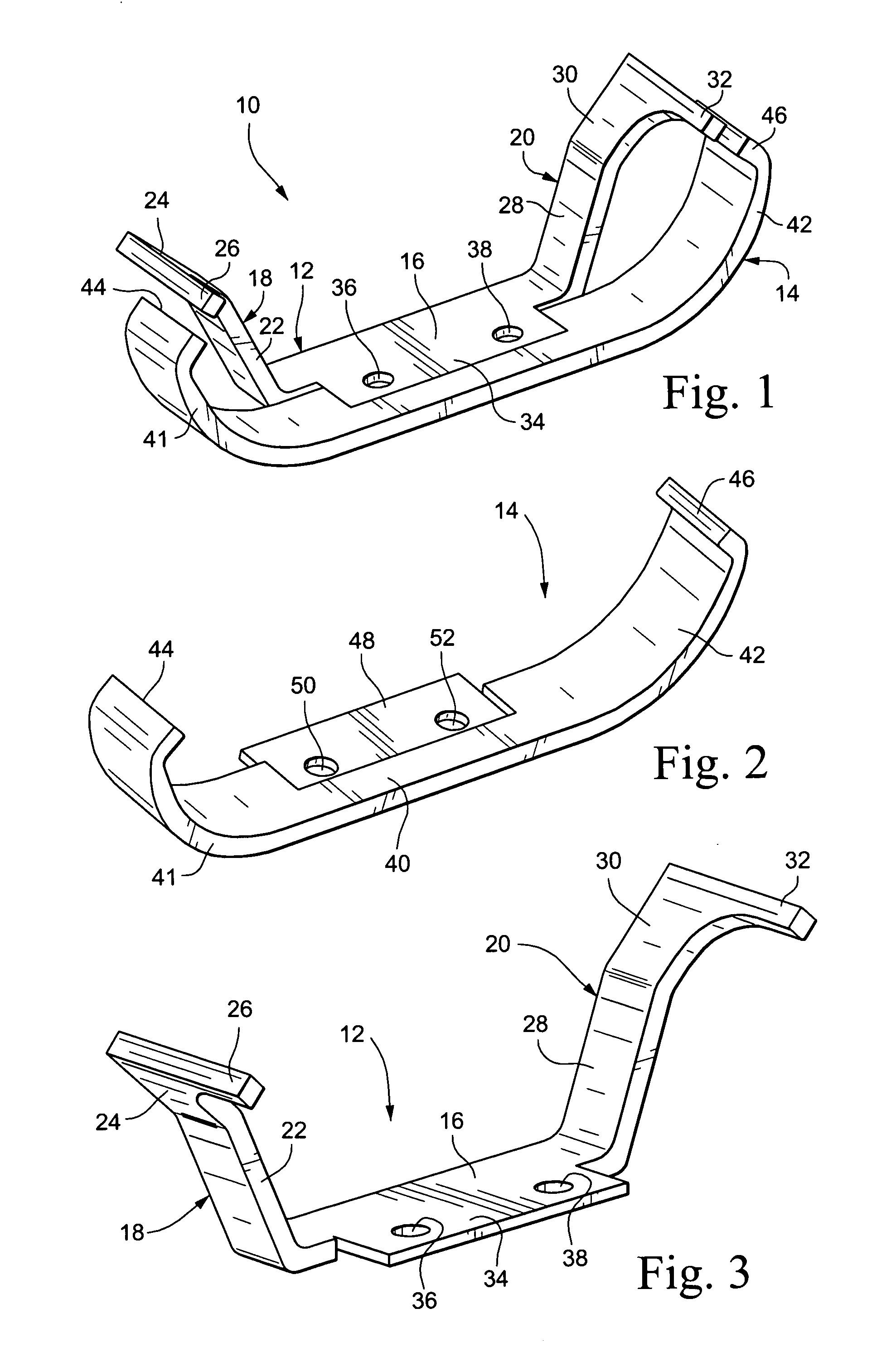
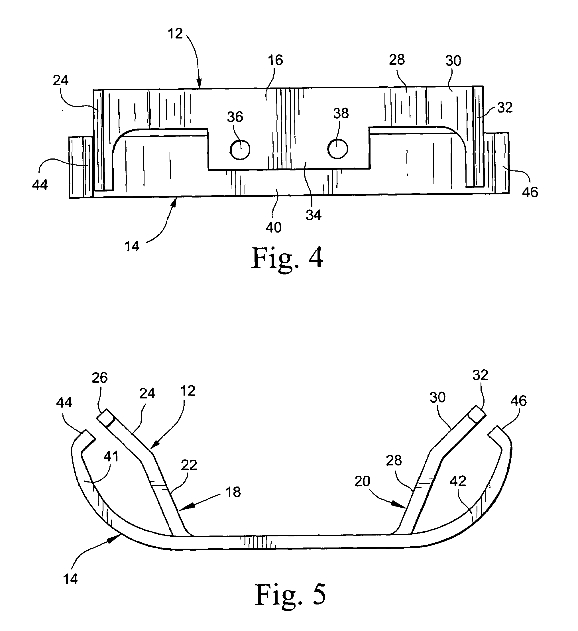
[0014]With reference initially to FIGS. 1-3, the two-piece mounting bracket assembly 10 in accordance with a non-limiting exemplary embodiment includes a first generally U-shaped bracket component 12 and a second generally U-shaped bracket component 14. While both components are broadly described as being of generally U-shape, it will be appreciated from the drawings and the detailed description below that the shapes of the components 12 and 14 are significantly different. Nevertheless, the shapes of the components 12 and 14 may vary within the scope of the invention. Specific shapes may be dictated, for example, by the locations of the bracket mounting surfaces as found on the mounting platforms 34, 48 described below, in relation to the locations of associated H-blocks on the transition piece (see H-blocks 62 on transition piece 54 in FIG. 6), with due consideration for adequate clearance to access nearby components.

[0015]The first bracket component 12 includes a substantially fla...


PUM


Abstract

A mounting bracket assembly includes: a first bracket component having a first pair of laterally spaced securement tabs; a second bracket component having a second pair of laterally spaced securement tabs; wherein said first and second bracket components are engageable with each other such that respective ones of each of the first and second pairs of securement tabs are located adjacent each other and adapted to engage corresponding pairs of recesses in a machine component. A related method of securing a transition piece to a combustor casing without welding includes: providing a first mounting bracket component for attaching the transition piece to a turbine combustor casing, the first mounting bracket formed with a first set of securement tabs; providing a second mounting bracket component that is usable with the first bracket component, the second mounting bracket component formed with a second set of securement tabs; and slidably engaging the transition piece with the first and second mounting bracket components, such that the first and second pairs of securement tabs are received within corresponding axially-aligned recesses provided on the transition piece, thereby permitting the transition piece to grow thermally relative to the first and second mounting bracket components.

Description

[0001]This application relates generally to gas turbine combustor technology and, more specifically, to a mounting arrangement for the forward end of a transition piece (or duct) that carries hot gases from a combustor to a first stage of the turbine.BACKGROUND OF THE INVENTION[0002]The transition piece forward mounting bracket is a component of the turbine combustion system that supports a transition duct (commonly referred to as the “transition piece”), that extends between a combustor liner or casing and a first turbine stage in a can-annular gas turbine combustion configuration. The mounting bracket generally requires replacement after completion of a specified number of hours in operation (e.g., 8000 hours) because high stresses and wear in this area could possibly result in failure of the turbine. There are instances, however, where it would be desirable to increase the service life without significant cost increases.BRIEF DESCRIPTION OF THE INVENTION[0003]This invention provi...

Claims


Application Information

Patent Timeline
IPC IPC(8): F16M7/00F16M11/00
CPCF23R3/60F01D9/023
Inventor MELTON, PATRICKKIDDER, KYLE
Owner GENERAL ELECTRIC CO
Why Eureka
Try Eureka