Engine generator

a generator and engine technology, applied in the direction of machines/engines, mechanical equipment, transportation and packaging, etc., can solve the problems of engine generators susceptible to tilting or overturning in a direction, and achieve the effect of reducing the weight of the engine generator, increasing and ensuring the stiffness of the bottom cover

Active Publication Date: 2009-12-31
HONDA MOTOR CO LTD
View PDF3 Cites 4 Cited by
  • Summary
  • Abstract
  • Description
  • Claims
  • Application Information

AI Technical Summary

Benefits of technology

[0006]It is therefore an object of the present invention to provide an engine generator capable of maintaining a stable orientation during transportation.

Problems solved by technology

Therefore, when the engine generator is being moved on uneven ground or similar terrain by lifting the left and right grips and causing the wheels to rotate, the engine generator is susceptible to tilting or overturning in a direction orthogonal to the direction of movement of the engine generator, in other words, in a direction of the width of the engine generator.

Method used


Image

  • Engine generator
  • Engine generator
  • Engine generator

Examples


Embodiment Construction

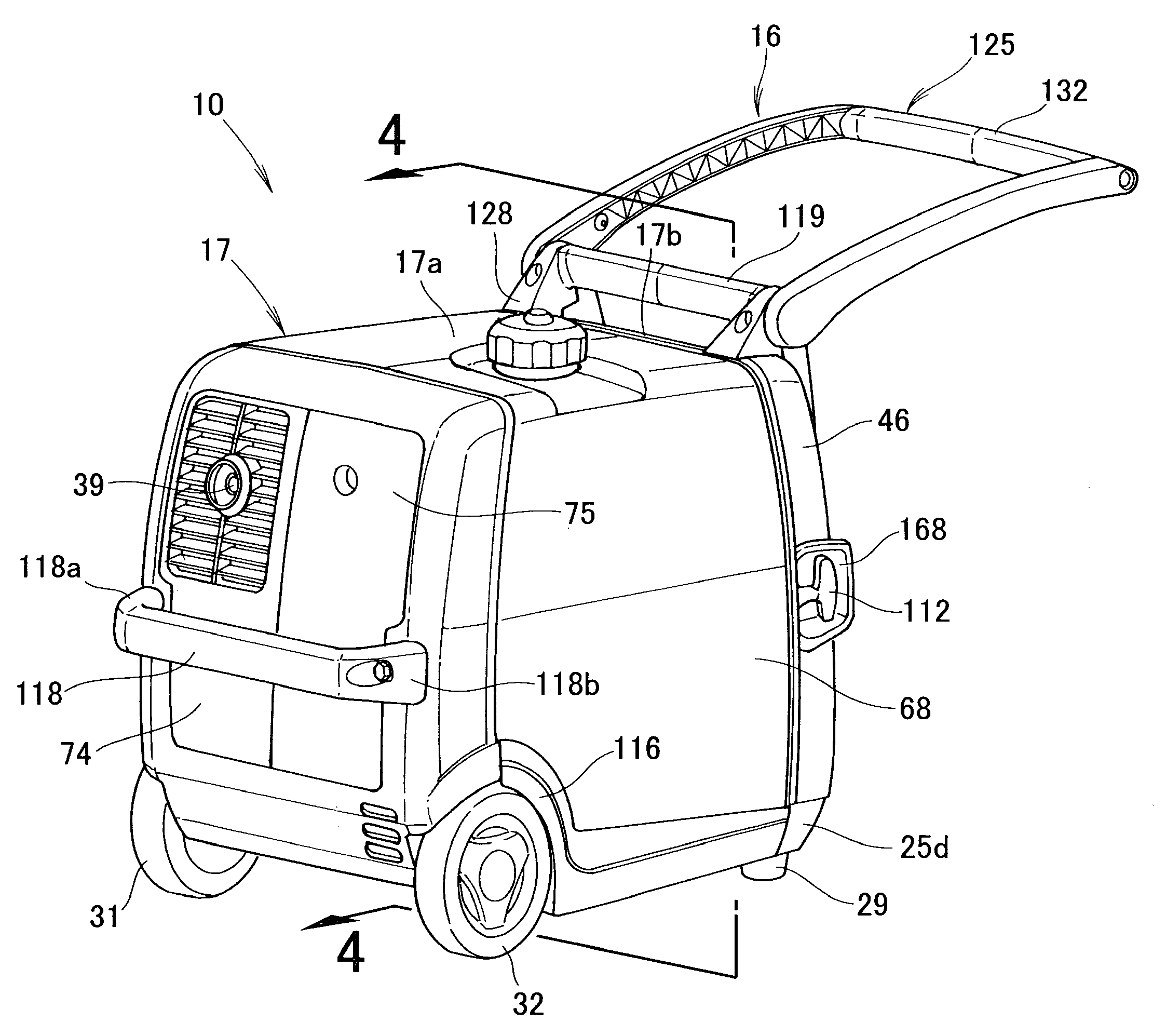
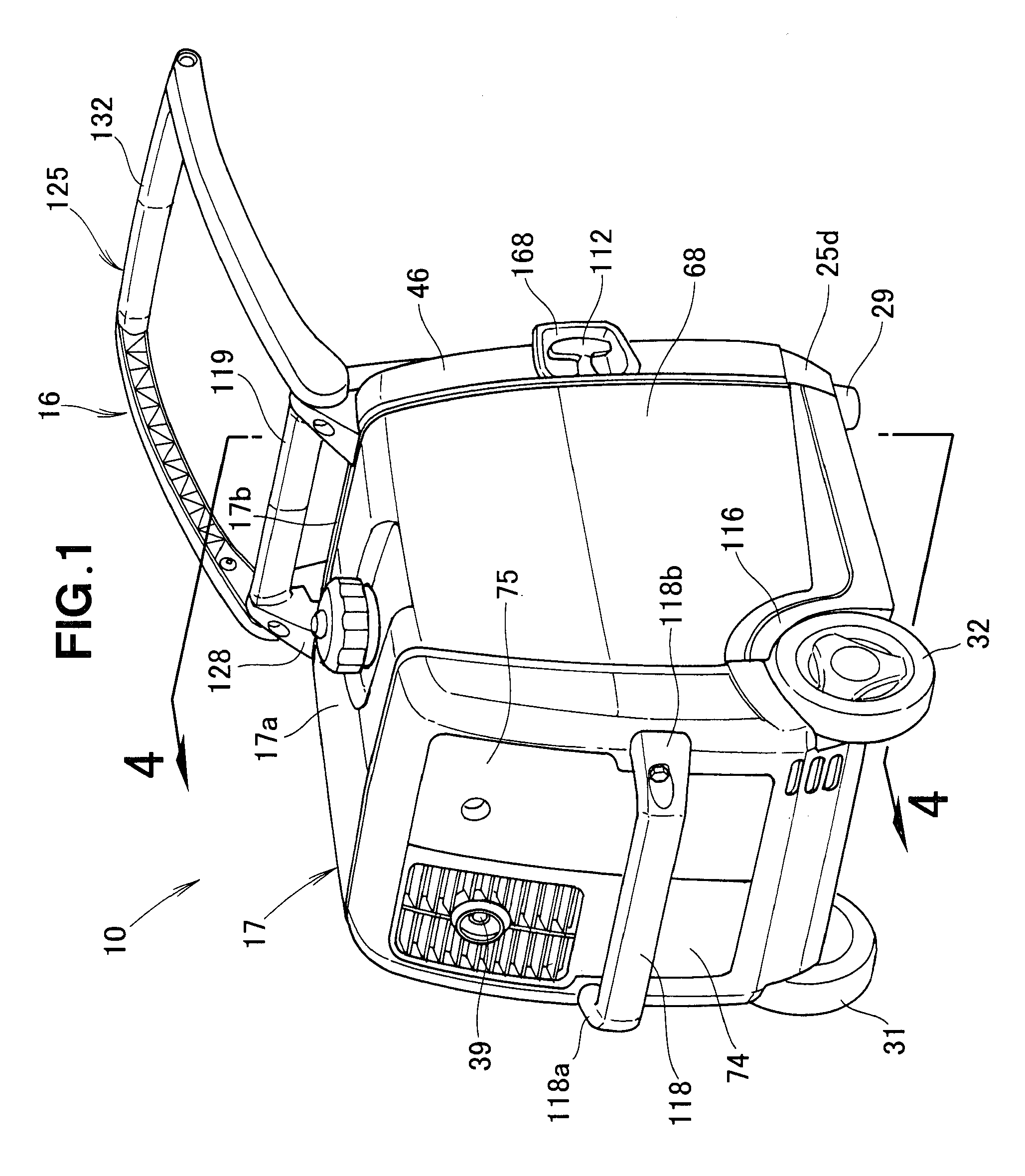
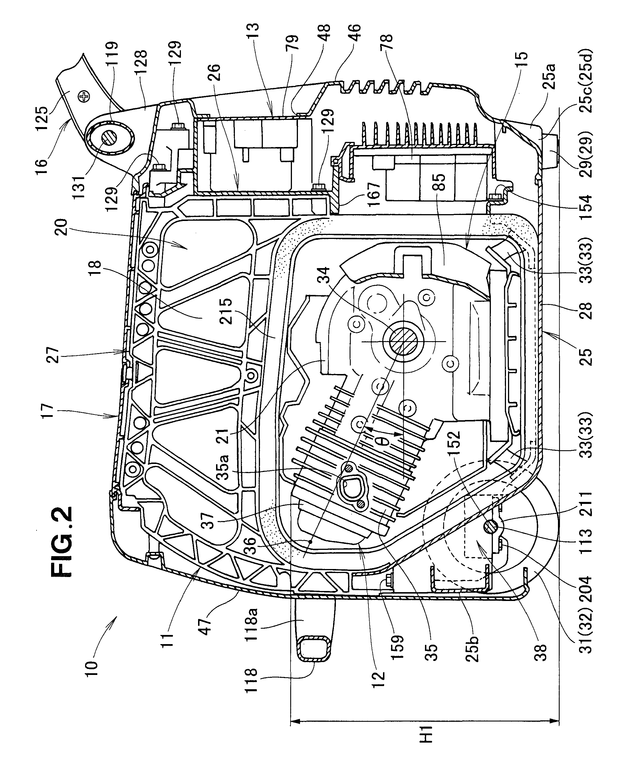
[0030]As shown in FIG. 1 and FIG. 2, an engine generator 10 comprises: a skeletal member 11; an engine / generator unit 12 provided to the skeletal member 11; an electrical component section 13 for controlling the output of the engine / generator unit 12; an intake / fuel feed mechanism 14 (see FIG. 4) for feeding fuel to the engine / generator unit 12; a cooling structure 15 for directing cooling air to the engine / generator unit 12; a transport structure 16 for transporting the engine generator 10; a case 17 for covering the engine / generator unit 12 and the electrical component section 13; an insulating member 18 for partitioning accommodation space 20 inside the case 17; and a muffler 23 (see FIG. 4) provided to an engine 21 of the engine / generator unit 12.

[0031]The engine generator 10 has left and right leg sections 29 provided to left and right corner sections 25c, 25d (see FIG. 5) of a front-end part 25a of the bottom cover 25 constituting the bottom section of the skeletal member 11, ...


PUM


Abstract

An engine generator movable on left and right wheels. The wheels are provided on a rear section of a bottom cover via an axle. A cylinder of an engine is disposed so as to incline upwards towards the direction of the axle. Inclining the cylinder lowers the center of gravity of the engine and disposes the axle positioned below the cylinder at a high position, thereby reducing the height of the engine generator. The orientation of the engine generator during travel is stabilized.

Description

FIELD OF THE INVENTION[0001]The present invention relates to an engine generator having wheels, a case accommodating an engine and a draw handle extending upwardly from a front upper part of the case.BACKGROUND OF THE INVENTION[0002]An engine generator of this type is already known as disclosed in Japanese Patent Application Laid-Open Publication No. 2005-76550 (JP 2005-076550 A).[0003]The known engine generator comprises a bottom cover to which leg sections and wheels are provided, an engine provided to the bottom cover via an attachment member and accommodated in a case, and a handle for transportation provided to the front section, which is the opposite side of the wheels.[0004]The handle for transportation extends from left and right end sections of the case substantially horizontal to the direction in which the handle lever separates from the case, and grips are provided to the distal ends of the left and right handle levers.[0005]According to the engine generator, grasping and...

Claims


Application Information

Patent Timeline
Patent Type & Authority Applications(United States)
IPC IPC(8): B62B1/20
CPCF02B63/047F02B63/04F02B77/00
Inventor HIROSE, TADAFUMISHIN, MASANORIUCHIMI, MAKOTOAOKI, TAKAYUKI
Owner HONDA MOTOR CO LTD
Why Eureka
Try Eureka