Method for manufacturing liquid crystal electro-optical module

A liquid crystal, electro-optical technology, applied in optics, nonlinear optics, instruments, etc., can solve the problems of alignment processing, difficult liquid crystal molecules, etc.

Active Publication Date: 2018-05-11
黄素真
View PDF6 Cites 3 Cited by
  • Summary
  • Abstract
  • Description
  • Claims
  • Application Information

AI Technical Summary

Problems solved by technology

[0010] In order to successfully combine liquid crystal materials with hollow optical fibers and apply them to the development of highly tuned optical fibers or electro-optical components, it is necessary to solve the problem that it is difficult to align liquid crystal molecules in a narrow closed space (micrometer scale), and then improve liquid crystals. The disclination line generated by the opposite tilt of the molecule occurs

Method used


Image

  • Method for manufacturing liquid crystal electro-optical module
  • Method for manufacturing liquid crystal electro-optical module
  • Method for manufacturing liquid crystal electro-optical module

Examples


no. 1 example

[0055] [First embodiment: Gradient electric field experiment]

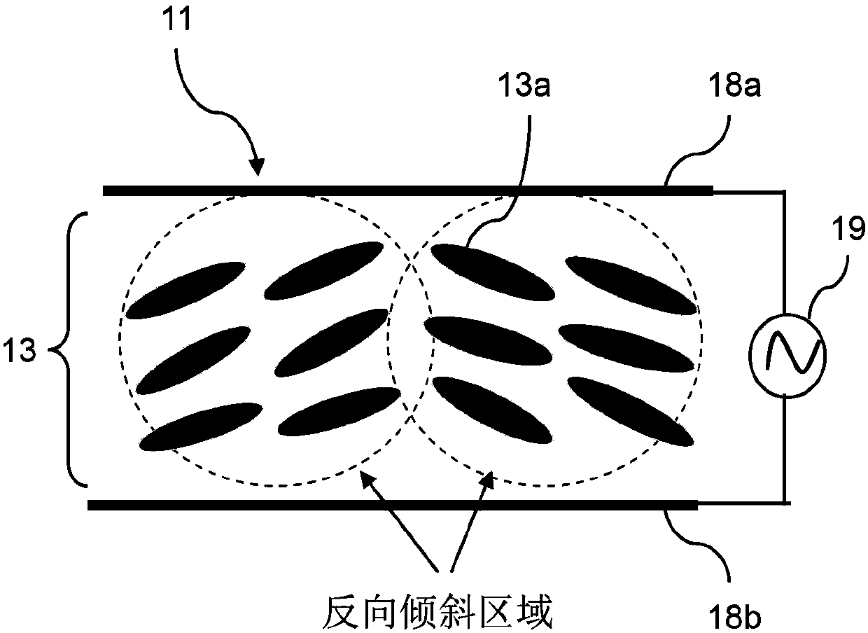
[0056] Step 1: In order to generate a gradient electric field in the experiment, the ITO film of the ITO (indium tin oxide, indium tin oxide) glass substrate is directly used as the electrode plate for supplying the external voltage.

[0057] Step 2: first attach the fiber or photonic crystal fiber filled with liquid crystal / photosensitive monomer mixture on the ITO glass substrate (lower electrode 48b), and then cover another ITO glass substrate (upper electrode 48a) on the upper end, as Figure 4 as shown in part (a).

[0058] Step 3: In order to generate a gradient electric field between the electrode plates, slightly tilt the upper electrode 48a so that it forms a small angle with the lower electrode 48b, as Figure 4 as shown in part (b).

[0059] Step 4: After applying a voltage, a gradient electric field can be formed between the upper electrode 48a and the lower electrode 48b. Subsequently, use a polari...

no. 2 example

[0068] [Second embodiment: Gradient temperature field experiment]

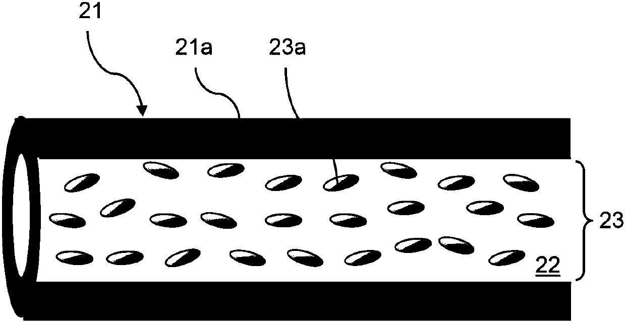
[0069] Step 1: Fix the liquid crystal optical fiber 51 between two electrode plates (not shown in the figure), and place it on the heating table 52, such as Figure 9 shown.

[0070] Step 2: In order to generate the gradient temperature field, the method is as follows:

[0071] (1) The right side of the optical fiber 51A is raised (~2mm) by means of a heat-insulating spacer 57, so that the substrate is inclined and the farther to the right side it is from the heating surface of the heating table 52, the optical fiber 51A will be heated unevenly And the temperature distribution characteristics with a temperature gradient, such as Figure 9 shown. Or, (2) the right side of the optical fiber 51B is emptied and only the left side is in contact with the heating stage 52 (~70°C), so that the heated part on the left side of the optical fiber 51B exhibits the highest temperature, and the temperature increases with ...


PUM


Abstract

The invention provides a method for manufacturing a liquid crystal electro-optical module. According to the method, liquid crystal alignment is performed in a non-contact manner to provide stable alignment of liquid crystal molecules sealed in the liquid crystal electro-optical module, so that the liquid crystal molecules have a pre-tilt angle defined in a steady state, and thus liquid crystal canbe prevented from defects caused by reverse tilt when an applied field tends to be dynamic. The method includes the steps of providing an optical unit including a hollow space; injecting a liquid crystal mixture into the hollow space; and applying a gradient field to the liquid crystal mixture, wherein the intensity of the gradient field shows a gradient distribution.

Description

technical field [0001] The present invention relates to a method for manufacturing liquid crystal electro-optical components, in particular to a non-contact method for aligning liquid crystals, providing the liquid crystal molecules sealed in the liquid crystal electro-optic components to achieve a stable alignment effect, so that the liquid crystal molecules have a stable state in a stable state. The defined pre-tilt angle can prevent the occurrence of defects caused by the reverse tilt of the liquid crystal molecules when the external electric field tends to move. Background technique [0002] When combining liquid crystal (LC) materials with hollow optical fibers, photonic crystals or closed structures to develop novel electro-optical components, it is difficult to effectively control the liquid crystal molecules into a stable arrangement in the hollow column, making the liquid crystal molecules Disclination lines (also called discontinuity lines) of alignment defects wil...

Claims


Application Information

Patent Timeline
Patent Type & Authority Applications(China)
IPC IPC(8): G02F1/1337
CPCG02F1/133788
Inventor 黄素真苏贤宾何柏彦张孟筑林颍
Owner 黄素真
Why Eureka
Try Eureka