
Power measurement apparatus

a technology of power measurement and power meter, which is applied in the direction of ac/dc measuring bridges, instruments, and base element modifications, etc., can solve the problems of high cost of rf testing instruments such as the described power meter, and the high cost of batch production of rf devices

Active Publication Date: 2009-12-31
HONG FU JIN PRECISION IND (SHENZHEN) CO LTD +1
View PDF1 Cites 31 Cited by
  • Summary
  • Abstract
  • Description
  • Claims
  • Application Information

AI Technical Summary

Benefits of technology

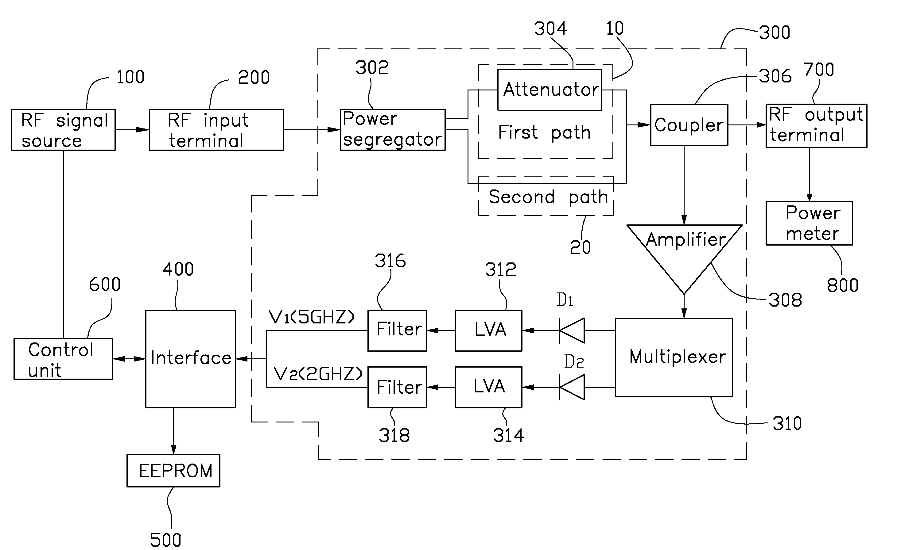
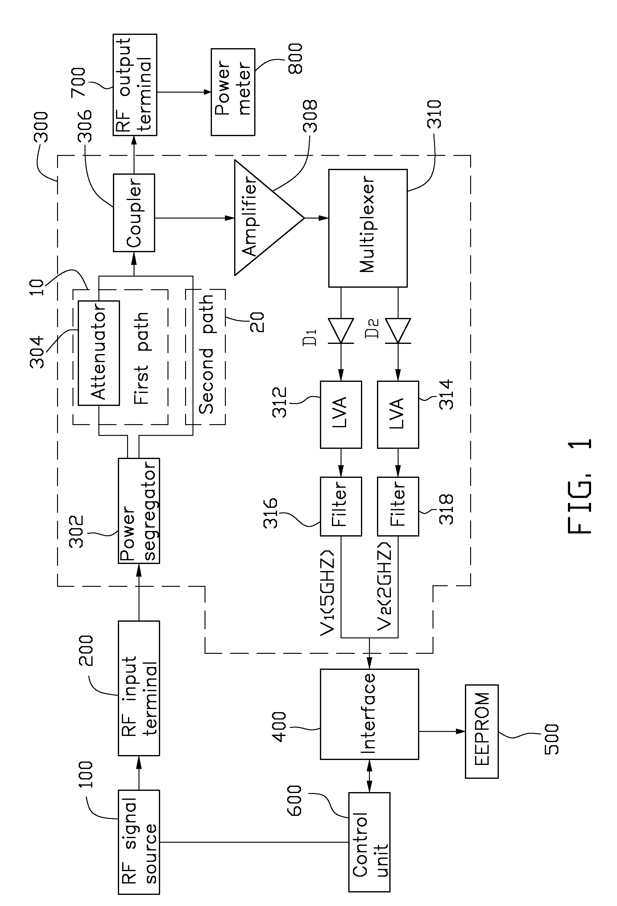
[0008]Referring to FIG. 1, a power measurement apparatus in accordance with an embodiment of the disclosure is configured to measure power output from a radio-frequency (RF) device. The power measurement apparatus includes an RF input terminal 200, a measurement module 300, an interface 400, an electrically erasable programmable read-only memory (EEPROM) 500, a control unit 600, and an RF output terminal 700.

Problems solved by technology

However, RF testing instruments, such as the described power meter, are costly.
Batch productions of RF devices are especially costly due to the necessity for multiple RF testing instruments.

Method used


Image

  • Power measurement apparatus
  • Power measurement apparatus
  • Power measurement apparatus

Examples


Embodiment Construction

[0008]Referring to FIG. 1, a power measurement apparatus in accordance with an embodiment of the disclosure is configured to measure power output from a radio-frequency (RF) device. The power measurement apparatus includes an RF input terminal 200, a measurement module 300, an interface 400, an electrically erasable programmable read-only memory (EEPROM) 500, a control unit 600, and an RF output terminal 700.

[0009]The RF input terminal 200 is connected to an RF signal source 100 and / or an RF device (not shown). The RF signal source 100 provides a series of predetermined RF signals with which the power measurement apparatus can generate a voltage-power table (VPT). The EEPROM 500 is configured to store the VPT. The power measurement apparatus thus obtains the power value of the RF device by querying the VPT. The interface 400 includes a universal asynchronous receiver and transmitter (UART) to communicate with the measurement module 300, the EEPROM 500, and the control unit 600. The ...


PUM

PropertyMeasurementUnit
frequency bandaaaaaaaaaa
power measurementaaaaaaaaaa

Abstract

A power measurement apparatus includes a radio frequency input terminal, a measurement module, an interface, a memory, and a control unit. The radio frequency input terminal is connected to a radio frequency device. The measurement module is connected to the radio frequency input terminal to convert the radio frequency signal into a voltage signal. The interface is connected to the measurement module, receiving and transmitting the voltage signal from the measurement module. The memory is connected to the interface to store a voltage-power table related to the radio frequency signal. The control unit is connected to the interface to query the voltage-power table in the memory via the interface, and obtain the power of the radio frequency device according to the voltage signal output from the measurement module.

Description

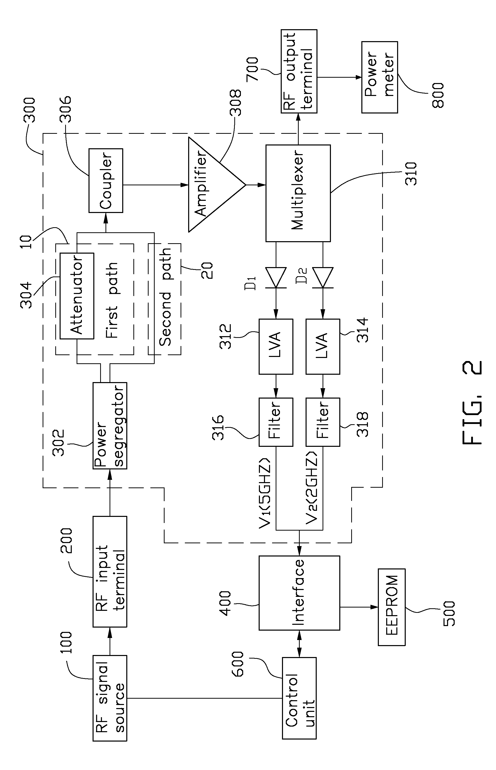
BACKGROUND[0001]1. Field of the Disclosure[0002]The disclosure relates to power measurement apparatuses, and particularly to an apparatus testing RF power during device manufacture.[0003]2. Description of the Related Art[0004]Typically, performance testing is required for RF devices during manufacture. Such tests may include employing a power meter to obtain an accurate measurement of the RF power. However, RF testing instruments, such as the described power meter, are costly. Batch productions of RF devices are especially costly due to the necessity for multiple RF testing instruments.BRIEF DESCRIPTION OF THE DRAWING[0005]FIG. 1 is a circuit diagram of an embodiment of a power measurement apparatus in accordance with the disclosure.[0006]FIG. 2 is a circuit diagram of another embodiment of a power measurement apparatus in accordance with the disclosure.[0007]FIG. 3 is a flow chart of a method of creating a voltage-power table applied to the power measurement apparatus of FIG. 1.DET...

Claims


Application Information

Patent Timeline
Patent Type & Authority Applications(United States)
IPC IPC(8): G01R21/06G01R3/00
CPCY10T29/49002G01R21/01
Inventor ZHANG, CHONGCHUNG, CHO-JUCHU, TENG-HUEI
Owner HONG FU JIN PRECISION IND (SHENZHEN) CO LTD
Learn More