
High-frequency switching-type direct-current rectifier

a direct-current rectifier, high-frequency switching technology, applied in transformers, transformers/inductance details, electrical equipment, etc., can solve the problems of large energy and power consumption, high iron loss and copper loss, and large volume, and achieve the effect of easy appreciation of the improvement of the conventional transformer

Inactive Publication Date: 2009-12-31
LIN HSUN I
View PDF17 Cites 21 Cited by
  • Summary
  • Abstract
  • Description
  • Claims
  • Application Information

AI Technical Summary

Benefits of technology

The present invention provides a new design for a transformer used in a high-frequency switching-type DC rectifier. The transformer is made of a ring-shaped iron core with a primary side wound with copper wire and a secondary side with a new module or block that is also wired with copper. The secondary-side module or block is cooled with water to maintain normal temperatures, improving the performance of the transformer and reducing its size and weight. The cooling water can be recollected and does not cause pollution. Overall, the new transformer design improves energy and power saving, and reduces the size and weight of the transformer.

Problems solved by technology

To cope with the needs of large current and low voltage, the transformer of the SCR suffers high iron loss and copper loss, is of low efficiency, consumes a large amount of energy and power, and is bulky.
For example, a cooling fan can be employed to carry out forced cooling, but the cooling fan causes large noises.
Another example is to use oil cooling and this often causes pollution and has a poor rectification performance

Method used


Image

  • High-frequency switching-type direct-current rectifier
  • High-frequency switching-type direct-current rectifier
  • High-frequency switching-type direct-current rectifier

Examples


first embodiment

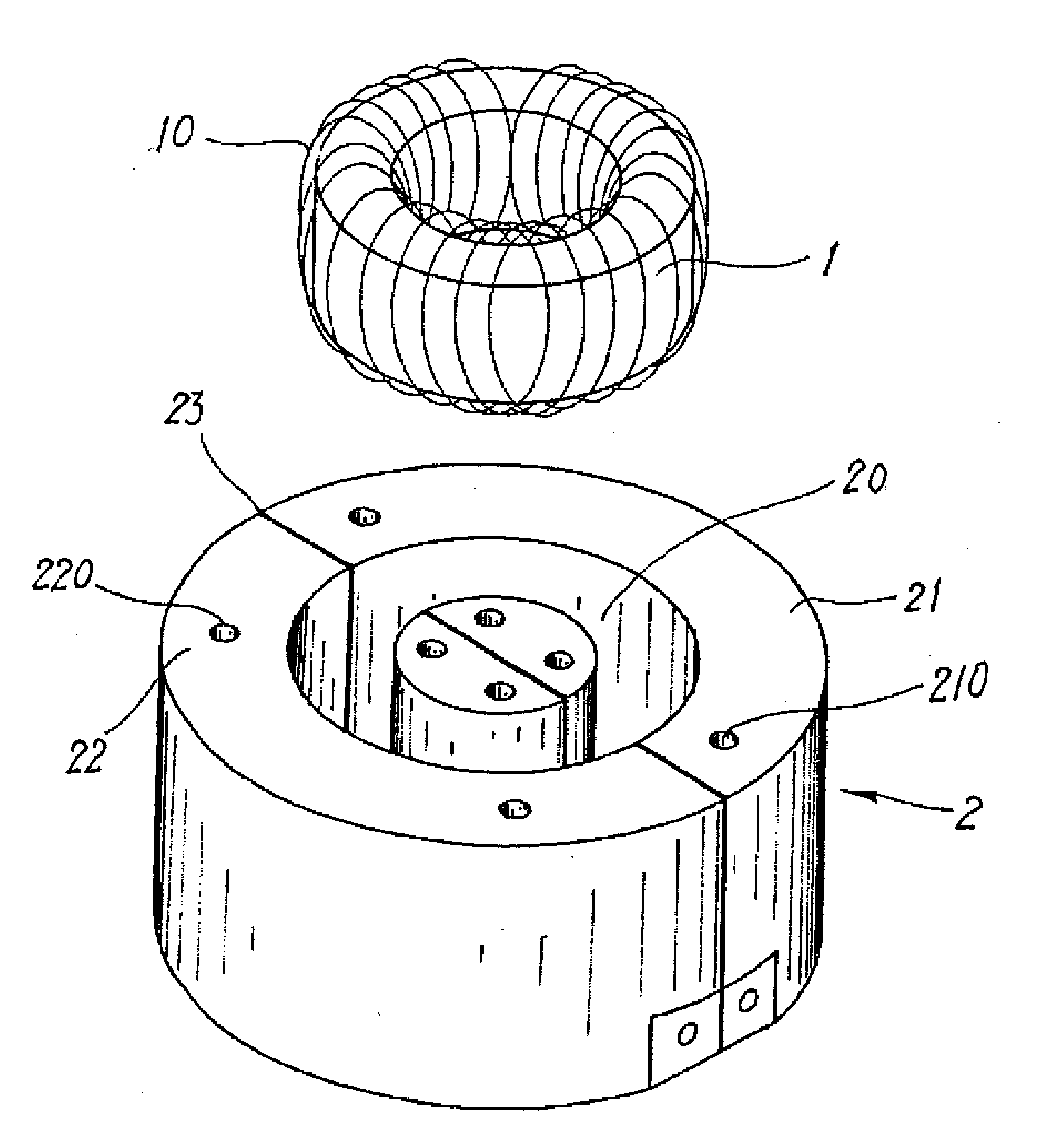
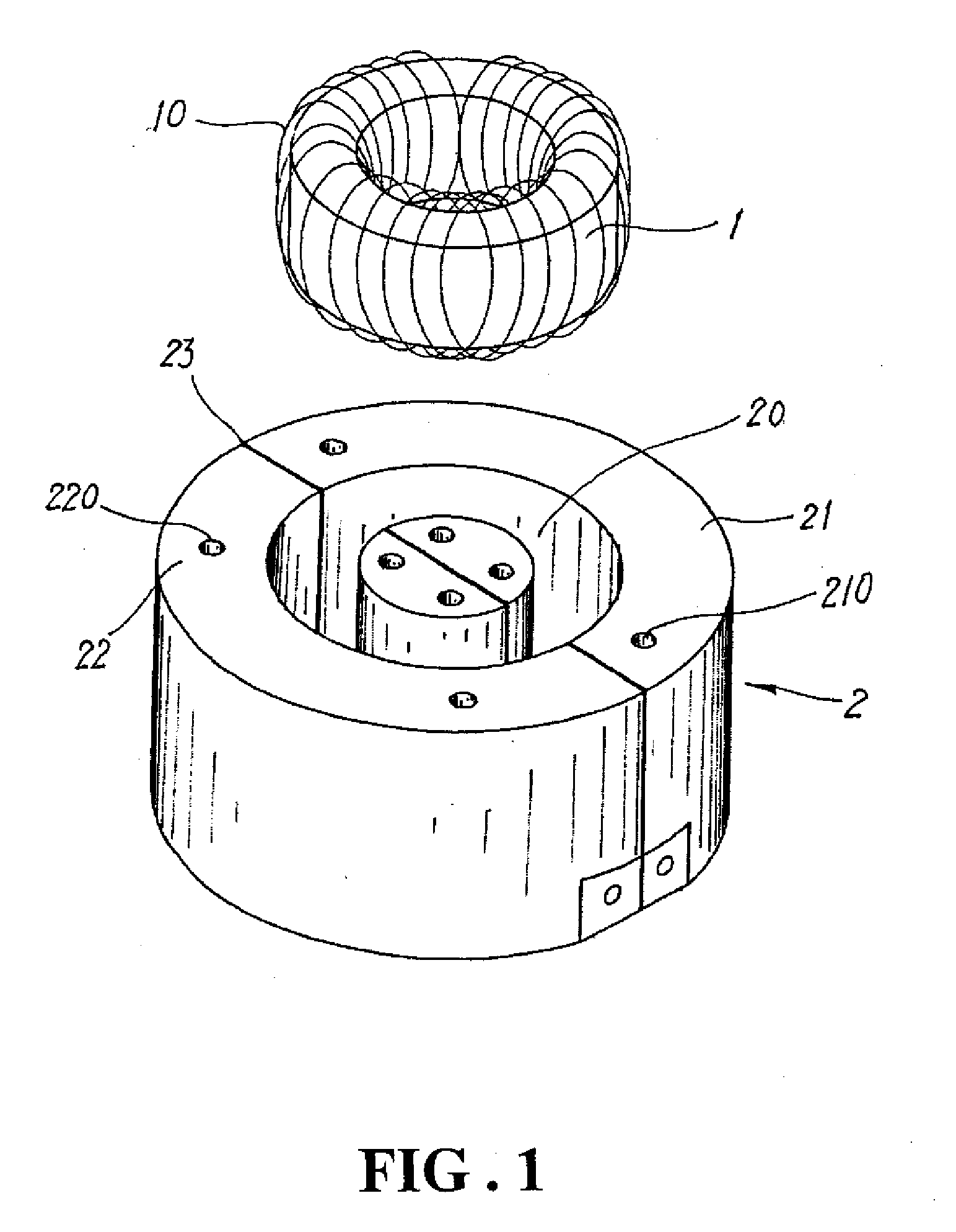
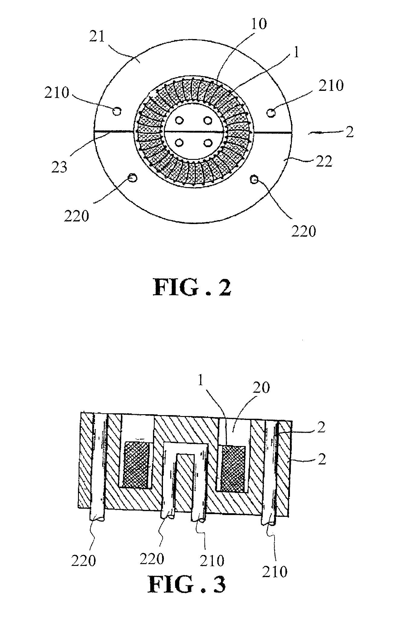
[0017]With reference to the drawings and in particular to FIG. 1, which shows an exploded view of a transformer constructed in accordance with the present invention, the transformer comprises a ring-shaped iron core 1 and a secondary-side module (block) 2. The ring-shaped iron core 1 is provided with a primary-side winding 10, which is formed by winding copper wire(s). The secondary-side module 2 is formed of two combined semi-cylindrical blocks 21, 22 having a centrally located ring-shaped groove 20 and isolated by insulator 23. The secondary-side module 2 also forms therein at least one cooling water tube that forms at least one cooling water inlet hole 210 and at least one cooling water outlet hole 220.

[0018]Also referring to FIG. 2, the transformer of the present invention, which is different from a conventional transformer that is made of silicon steel plates provided for a silicon-controlled rectifier (SCR) and a conventional large-current low-voltage transformer for a high-fr...

second embodiment

[0020]With reference to FIG. 4, which shows a perspective view of the present invention, a secondary-side module 3 forms a first, centrally-located ring-shaped groove 30 and the secondary-side module 3 is divided into four segments or blocks 31, 32, 33, 34. When assembled, joining faces of each block are isolated by insulators 35. Each block similarly forms a cooling water inlet hole 36 and a cooling water outlet hole 37, so that during the operation of rectification, each block can be cooled and maintains at a normal temperature to enhance the performance of the transformer.

third embodiment

[0021]Further, in accordance with the present invention, the secondary-side module can be modified to have a rectangular shape, as shown in FIG. 5, which illustrates a perspective view of the present invention. The secondary-side module 3 is comprised of two rectangular blocks 41, 42, which are symmetric with respect to each other and define a centrally-located ring-shaped groove 40 therebetween for receiving the ring-shaped iron core 1. The blocks 41, 42 forms cooling water inlet holes 43 and cooling water outlet holes 44. Joining faces of the blocks 41, 42 are similarly isolated by insulators 45, so as to be fit for large-current low-voltage operation and having extremely high rectification efficiency.


PUM

PropertyMeasurementUnit
voltageaaaaaaaaaa
voltageaaaaaaaaaa
sizeaaaaaaaaaa

Abstract

The present invention relates to a novel structure of a transformer for a high-frequency switching-type direct-current (DC) rectifier, and particularly to an improved structure of a transformer applicable to a large-current low-voltage high-frequency switching-type rectifier, wherein the transformer is comprised of a ring-shaped iron core (made of materials such as dust core or nanometer crystalline silicon or amorphous silicone), which is provided with a primary side formed with winding(s) of copper wire(s), coupling with a secondary side that is formed with a newly-developed module or block, which replaces the secondary side that was constructed to provide output with copper wires or copper plate with wire wound thereon. A cooling water tube is arranged in the secondary-side module to remove heat with the water so as to maintain normal temperatures of the transformer in a pollution-free manner with reduced size and weight and easy assembling and reduced costs of the transformer.

Description

BACKGROUND OF THE INVENTION[0001](a) Technical Field of the Invention[0002]The present invention relates to an improved structure of a large-current low-voltage transformer for a high-frequency switching-type direct-current (DC) rectifier, wherein the transformer is comprised of a ring-shaped iron core (made of materials such as dust core or nanometer crystalline silicon or amorphous silicone), which is provided with a primary side formed with winding(s) of copper wire(s) and has a secondary side that supplies an output of large current and low voltage. The secondary side is made in the form of a modular or block unit to thereby provide a novel transformer. The large amount of heat generated by the operation of the large-current low-voltage transformer is removed by cooling water by arranged a cooling water tube inside the modular unit so that the performance of the large-current low-voltage high-frequency switching-type transformer is enhanced with reduced consumption of energy and...

Claims


Application Information

Patent Timeline
Patent Type & Authority Applications(United States)
IPC IPC(8): H01F27/08
CPCH01F27/16H01F27/255H01F30/16H01F30/04H01F27/2876
Inventor LIN, HSUN-I
Owner LIN HSUN I
Learn More