
Method and apparatus for real time enhancing of the operation of a fluid transport pipeline

a technology of fluid transport pipeline and real-time enhancement, which is applied in the direction of fluid tightness measurement, instrumentation, and measurement of fluid loss/gain rate, can solve the problem of requiring some level of attention for each destabilizing event, and achieve the effect of minimizing any long-term detrimental impact on the pipeline network

Active Publication Date: 2009-12-31
EXXON RES & ENG CO
View PDF15 Cites 67 Cited by
  • Summary
  • Abstract
  • Description
  • Claims
  • Application Information

AI Technical Summary

Benefits of technology

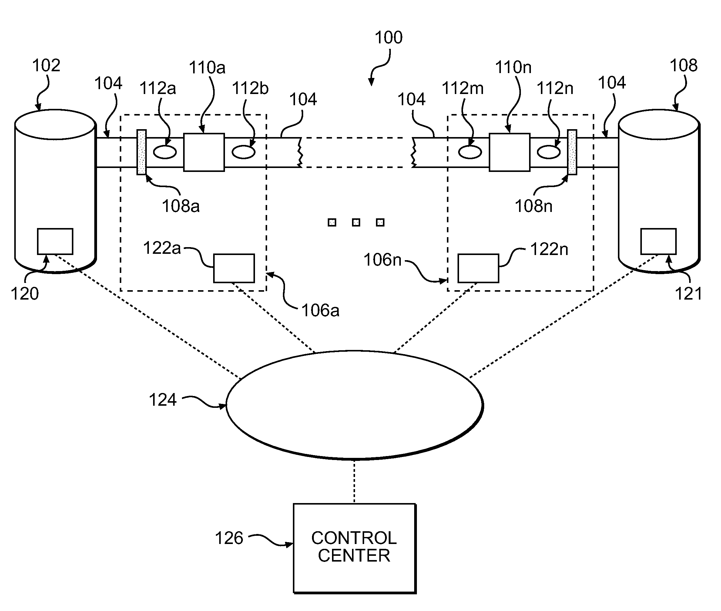
[0014]The method according to an aspect of the present invention may include sensing one or more pressure waves within the pipeline network at predetermined locations within the pipeline network, and determining the presence of a possible destabilizing event in the pipeline network in response to the sensed pressure waves. The destabilizing events can vary from a leak or rupture of the pipeline to a component failure in the field (e.g., a pump or valve or other pipeline equipment related to the operation of the pipeline) to a process error, which may attributed to an operator error (e.g., set point misplacement of a control valve or variable frequency drive adjustment) or misoperation of the pipeline. The destabilized events have varying degree of severity (with a potential leak or rupture having the highest level of severity). Nonetheless, each destabilizing event requires some level of attention. If a low level destabilizing event continues without implementing remedial measures steps, the efficient operation of the pipeline may be impacted, resulting in a potential fail safe operation (e.g., insufficient fluid feed to a pipeline pump, pressure within the pipeline is too high, component failure, etc.) By implementing corrective measures to stabilize the destabilizing event, potential ruptures and leaks can be prevented, stable operation is maintained, efficient pipeline operation is returned, damage to equipment is prevented and pipeline life may be extended (through reductions in strain, fatigue and wear on the pipeline).
[0016]In accordance with another aspect of the present invention, the method of monitoring the pipeline network may further comprise determining the location of the possible destabilizing event in the pipeline network in response to the sensed pressure waves. The presence and location of the possible destabilizing event may be reported to one or more operators of the pipeline network. In the event the destabilizing event is of a high level, the operator takes appropriate remedial measures (e.g., pump shutdown, setpoint adjustment, valve operation, system shutdown) to minimize the loss of fluid from the system and minimize the impact to the surrounding environment. Determining the location of a possible destabilizing event in the pipeline network in response to the sensed pressure waves may include identifying which predetermined locations a destabilizing event (e.g., a rupture) indicating pressure reaction is sensed at a first sensing time, then identifying which predetermined locations the sensed pressure wave is sensed at a second sensing time, and determining the location of a possible destabilizing event based upon the location of the sensed pressure wave at the first sensing time and the second sensing time. The plurality of coincidentally timed pressure reactions are analyzed to determine a probable location of the incident which caused the pressure reaction. The sensed reactions' chronology is compared for reasonableness against known parameters of the subject pipeline system and the fluid or fluid set within the pipeline.
[0021]It is another aspect of the present invention to provide a system that effectively provides for alarm management to reduce the number of the false alarms. During normal operation of the pipeline network, various steady-state and transient pressure profiles are generated that are not attributable to a destabilizing event, but nonetheless create pressure activity that generates an alarm signal. These can be attributed to normal pipeline operation and can be indicative of changes in operating mode and / or changes in operating events. For example, changing the operating mode from tight line mode to draw mode may create a pressure wave within the network giving rise to an alarm. Similarly, the normal operation of pumping units within the network (i.e., turning pumps on, off or adjusting a variable frequency drive) may create a pressure wave within the network giving rise to an alarm. These pressure waves reflect normal pipeline operation but may give rise to hundreds of false alarms on a daily basis. The dynamic nature of the system in accordance with the present invention provides effective alarm management to reduce the overall occurrence of the false alarms. This reduction in false alarms provides the pipeline operator with more time to address and respond to actual alarms as well as heighten the operator's sensitivity to actual alarms.
[0023]It is another aspect of the present invention to provide a monitoring system for detecting destabilizing events in a pipeline network and diagnosing the destabilizing events to identify (i) the location of the same and (ii) identify potential causes and remedial and / or corrective measures for the same. The system is especially useful in diagnosing both high level and lower level destabilizing events such that corrective measures can be implemented to minimize any long term detrimental impact on the pipeline network and to promptly return the network to stable operation.

Problems solved by technology

The destabilizing events can vary from a leak or rupture of the pipeline to a component failure in the field (e.g., a pump or valve or other pipeline equipment related to the operation of the pipeline) to a process error, which may attributed to an operator error (e.g., set point misplacement of a control valve or variable frequency drive adjustment) or misoperation of the pipeline.
Nonetheless, each destabilizing event requires some level of attention.

Method used


Image

  • Method and apparatus for real time enhancing of the operation of a fluid transport pipeline
  • Method and apparatus for real time enhancing of the operation of a fluid transport pipeline
  • Method and apparatus for real time enhancing of the operation of a fluid transport pipeline

Examples


Embodiment Construction

[0031]In the following detailed description and example, the invention will be described in connection with its preferred embodiments. However, to the extent that the following description is specific to a particular embodiment or a particular use of the invention, this is intended to be illustrative only. Accordingly, the invention is not limited to the specific embodiments described below, but rather, the invention includes all alternatives, modifications, and equivalents falling within the true scope of the appended claims.

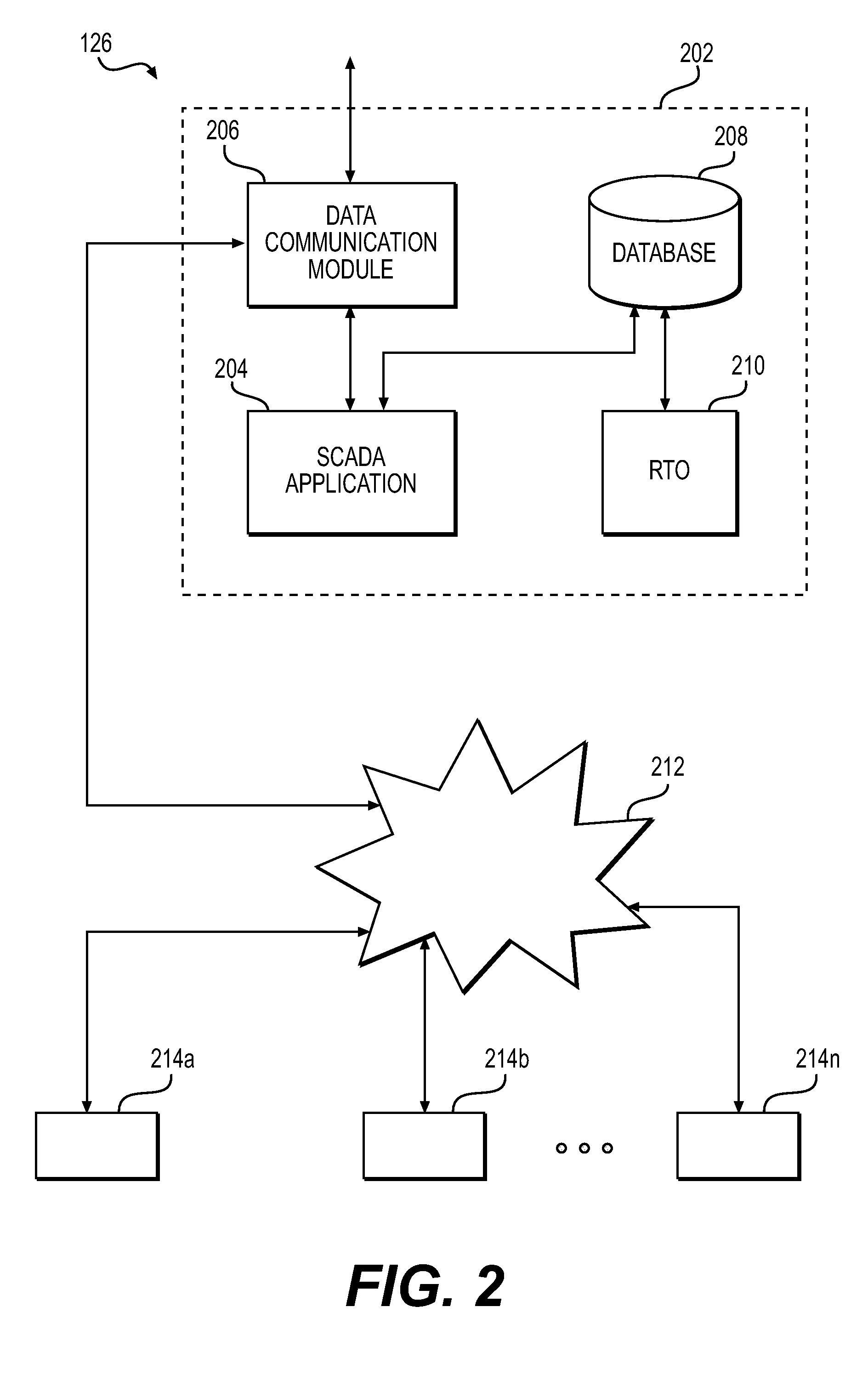
[0032]The present invention is directed to a system and method for detecting the occurrence of destabilizing events in one or more pipeline networks. The terminology “destabilizing event(s)” is intended to encompass any event or activity including but not limited to leaks, ruptures, equipment failures, equipment malfunction, process errors, etc that may have an adverse impact on the stable operation of the pipeline network. In particular, a real-time optimizer ...


PUM


Abstract

A real time method and dynamic logic-based system for enhancing the operation of a pipeline network is disclosed. The system and method perform monitoring of the operation of a pipeline network, generate alarms in response to differing levels of destabilized pipeline operations, manage the generation of alarms based upon known operating events and operating conditions, diagnose potential source of the detected destabilized events and manage the operation of the pipeline.

Description

CROSS REFERENCE TO RELATED PATENT APPLICATION[0001]This application relates and claims priority to U.S. Provisional Patent Application No. 61 / 129,466, filed on Jun. 27, 2008, entitled “A Method and Apparatus for Enhancing the Operation of a Fluid Transport Pipeline.”FIELD OF THE INVENTION[0002]The present invention relates to a method and system for enhancing the operation of a pipeline. In particular, the present invention is directed to a real time method and a dynamic, logic-based system for monitoring the operation of a pipeline network, generating alarms in response to differing levels of destabilized pipeline operations and managing the operation of the pipeline in response to the same. In particular, the present invention relates to a method and a dynamic behavior based system for the monitoring of a pipeline, and the detection and reporting of destabilized operating events including but not limited to possible pipeline rupture events based upon sensed hydraulic reactions wit...

Claims


Application Information

Patent Timeline
Patent Type & Authority Applications(United States)
IPC IPC(8): G08B21/00G01M3/28
CPCF17D5/06G08B21/18G01M3/04G01M3/2815Y10T137/0318Y10T137/0452
Inventor MCDOWELL, KEITH C.
Owner EXXON RES & ENG CO
Learn More