
Key sheet, key unit having thereof, and method of manufacturing keysheet

a key unit and key technology, applied in the direction of keyboard-like device coding, pulse technique, coding, etc., can solve the problems of inability to obtain decorative products, difficulty in providing different colors of illumination light to a conventional key sheet, and inability to provide predetermined different colors of illumination light to the keytops of different areas

Inactive Publication Date: 2009-12-31
SUNARROW CO LTD
View PDF2 Cites 17 Cited by
  • Summary
  • Abstract
  • Description
  • Claims
  • Application Information

AI Technical Summary

Benefits of technology

[0039]According to the first embodiment of the key sheet, since the key base is made of a transparent or translucent resin, the key base can be used as a light guiding means. Since the reflecting means which direct light emitted from the illumination-light emitting means toward the keytop-formed side are entirely or partially provided in each of the areas of the key base, the keytops can be illuminated with the light emitted from the illumination-light emitting means in each of the areas.
[0040]Since the key base is divided into the plurality of areas which includes one or more pad portions and the light-blocking portions are provided to the boundary regions between the adjacent areas of the key base, the keytops in each of the areas can be illuminated with the light emitted from the illumination-light emitting means in the area in a case where a key unit is constructed by assembling the key base on a circuit board, although different illumination-light emitting means are arranged in each area.

Problems solved by technology

As shown in FIG. 10, there is a problem that it is difficult to provide different colors of illumination light to a conventional key sheet.
On the other hand, with respect to the plurality of LEDs, although it is possible to make a color of the LED in one area and a color of the LED in another area different, some keytops may be illuminated with a mixed color of the plural colors of illumination light, thus making a problem that the predetermined different colors of illumination light cannot be provided to the keytops of the different areas, and a decorative product cannot be obtained.

Method used


Image

  • Key sheet, key unit having thereof, and method of manufacturing keysheet
  • Key sheet, key unit having thereof, and method of manufacturing keysheet
  • Key sheet, key unit having thereof, and method of manufacturing keysheet

Examples


embodiment 1

[0060]Hereinafter, embodiments of the present invention are described in detail.

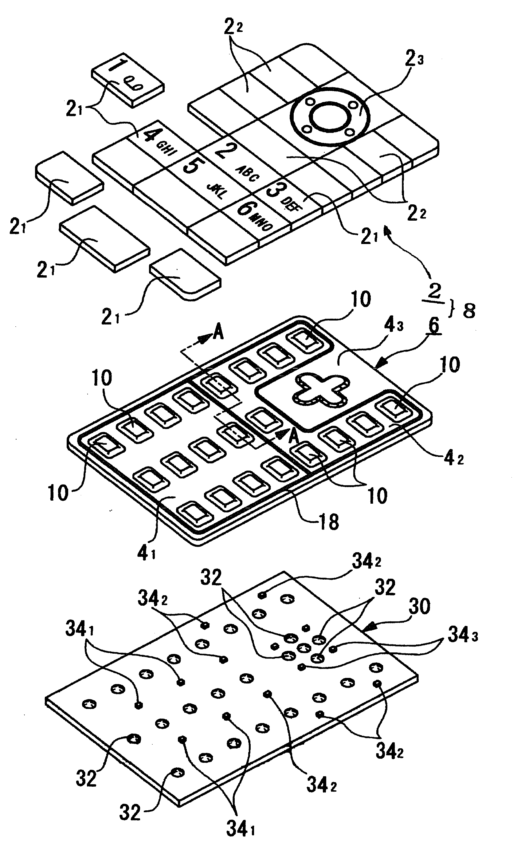
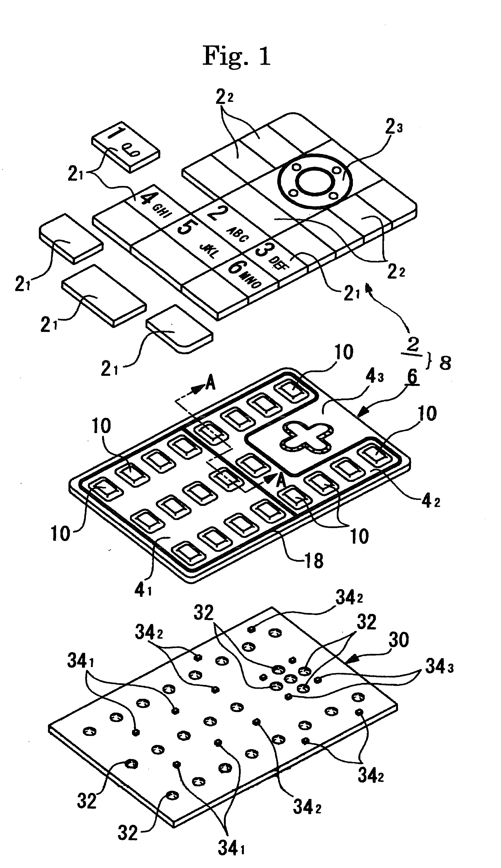
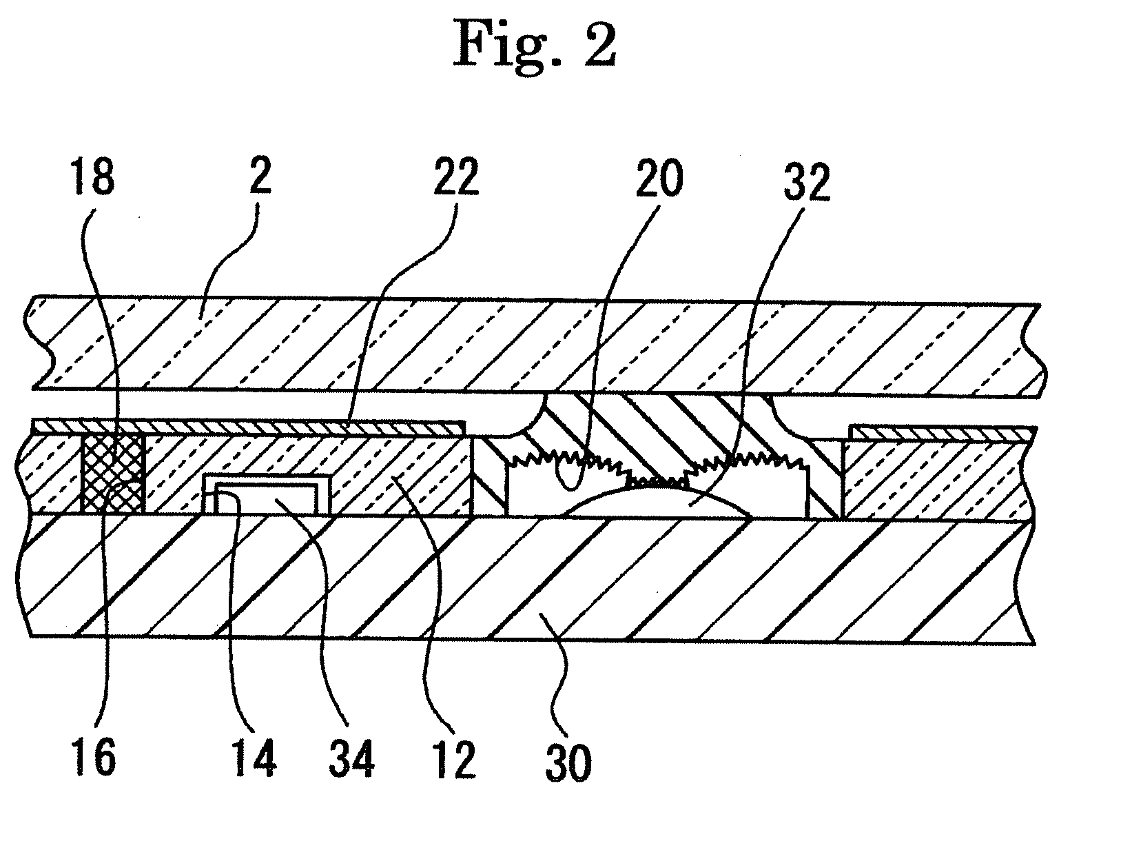
[0061]FIGS. 1 and 2 illustrate a first embodiment (Embodiment 1) of the present invention. FIG. 1 is a perspective exploded view of the embodiment, and FIG. 2 is a cross-sectional view thereof.

[0062]Reference number 2, 2, . . . denotes keytops which are made of a translucent resin. More specifically, the keytop is made of, for example, polycarbonate (PC), polyethylene terephthalate (PET), or polymethyl methacrylate (PMMA). Reference number 21, 21, . . . denotes the keytops 2, 2, . . . that are located in a first area 41. Similarly, reference number 22, 22, . . . denotes the keytops 2, 2, . . . that are located in a second area 42, and reference number 23, 23, . . . denotes the keytops 2, 2, that are located in a third area 43.

[0063]The areas 41, 42, and 43 are divided according to different colors of illumination light for the keytops 2, 2, . . . . Light-blocking portions (18) are provided to at least bo...

embodiment 2

[0076]FIGS. 3 and 4 illustrate a second embodiment (Embodiment 2) of the present invention. FIG. 3 is a perspective exploded view of the embodiment of the present invention. FIG. 4 is a cross-sectional view thereof.

[0077]The embodiment is different from the first embodiment in that all the portions (key pad portions and reinforcing portions) of the key base except for the light-blocking portions are integrally made of a resin such as a silicon rubber or an elastomer resin, but the other components are the same. The same components are denoted by the same reference numbers, and detailed description thereof is omitted. Hereinafter, only the difference is described in detail with reference to FIGS. 3 and 4.

[0078]Reference number 6a denotes a key base in which the key pad portions and the reinforcing portions are integrally made of the same resin, for example, a silicon rubber or an elastomer resin. However, only the light-blocking portions 18 are made of a different resin or metal havi...

embodiment 3

[0080]FIGS. 5(A) to 5(D) are cross-sectional views illustrating processes of an example (a third embodiment; Embodiment 3) of a method of manufacturing the reinforcing portions 12 of the key base 6 according to the first embodiment of the present invention.

[0081](A) A carrier base 50 made of, for example, a resin is prepared. On a surface of the carrier base 50, protrusions 52, 52, . . . where the illumination-light emitting means arrangement concave portions 14, 14, . . . are to be arranged are formed at each of positions where the LEDs 34, 34, . . . are to be arranged.

[0082]The carrier base 50 is entirely coated with a resin layer 12a for formation of the reinforcing portions by using, for example, spin-coating, and the resin is cured by using UV-light illumination or the like. Herein, the resin layer 12 is made of, for example, a UV-cured resin or the like with a thickness of about 0.3 mm to 2 mm. Reference number 14, 14, . . . denotes the illumination-light emitting means arrang...


PUM


Abstract

In order to provide different colors of illumination light to keytops in different areas, there is provided a key sheet 8 having a plurality of pad portions 10, 10, . . . provided on a key base 6 made of a transparent or translucent resin and a plurality of keytops 2 provided on the pad portions 10, 10, . . . , wherein the key base 6 is divided into a plurality of areas 41, 42, and 43 which includes one or a plurality of pad portions 10, 10, . . . ; light-blocking portions 18 are provided to boundary regions between the adjacent areas 4, 4 of the key base 6; at least one illumination-light emitting means arrangement portion 14 is provided so as to correspond to each of the areas 41, 42, and 43; and reflecting means 20 which direct light emitted from illumination-light emitting means toward keytop-formed side are entirely or partially arranged in each of the areas 41, 42, and 43 of the key base 6.

Description

TECHNICAL FIELD[0001]The present invention relates to an illumination-type key sheet used for an electronic apparatus, for example, a mobile phone, a PHS, a handheld terminal (PDA or the like), a portable audio apparatus, and a remote controller of home electric appliances, and a key unit having thereof, and a method of manufacturing the key sheet.BACKGROUND ART[0002]In key sheets used for electronic apparatuses, for example, a mobile phone, a PHS, a handheld terminal (PDA), a portable audio apparatus, or a remote controller of home electric appliances, many of them have keytops which are illuminated with a predetermined illumination-light emitting means (for example, a light-emitting device including light-emitting diodes). Accordingly, there is an advantage that keys can be visible in a dark place, so that the keys are easy to manipulate.[0003]The applicant has proposed various contrivances about an illumination-type key sheet or a key unit obtained by providing the key sheet on a...

Claims


Application Information

Patent Timeline
Patent Type & Authority Applications(United States)
IPC IPC(8): H03M11/00
CPCH01H13/83H01H13/88H01H2219/06H04M1/23H01H2229/048H01H2231/022H01H2219/064H01H11/00H01H13/70
Inventor YOSHIDA, MINORU
Owner SUNARROW CO LTD
Learn More