
Intelligent basketball

Inactive Publication Date: 2009-12-31
GOLD ROBERT S
View PDF26 Cites 96 Cited by
  • Summary
  • Abstract
  • Description
  • Claims
  • Application Information

AI Technical Summary

Benefits of technology

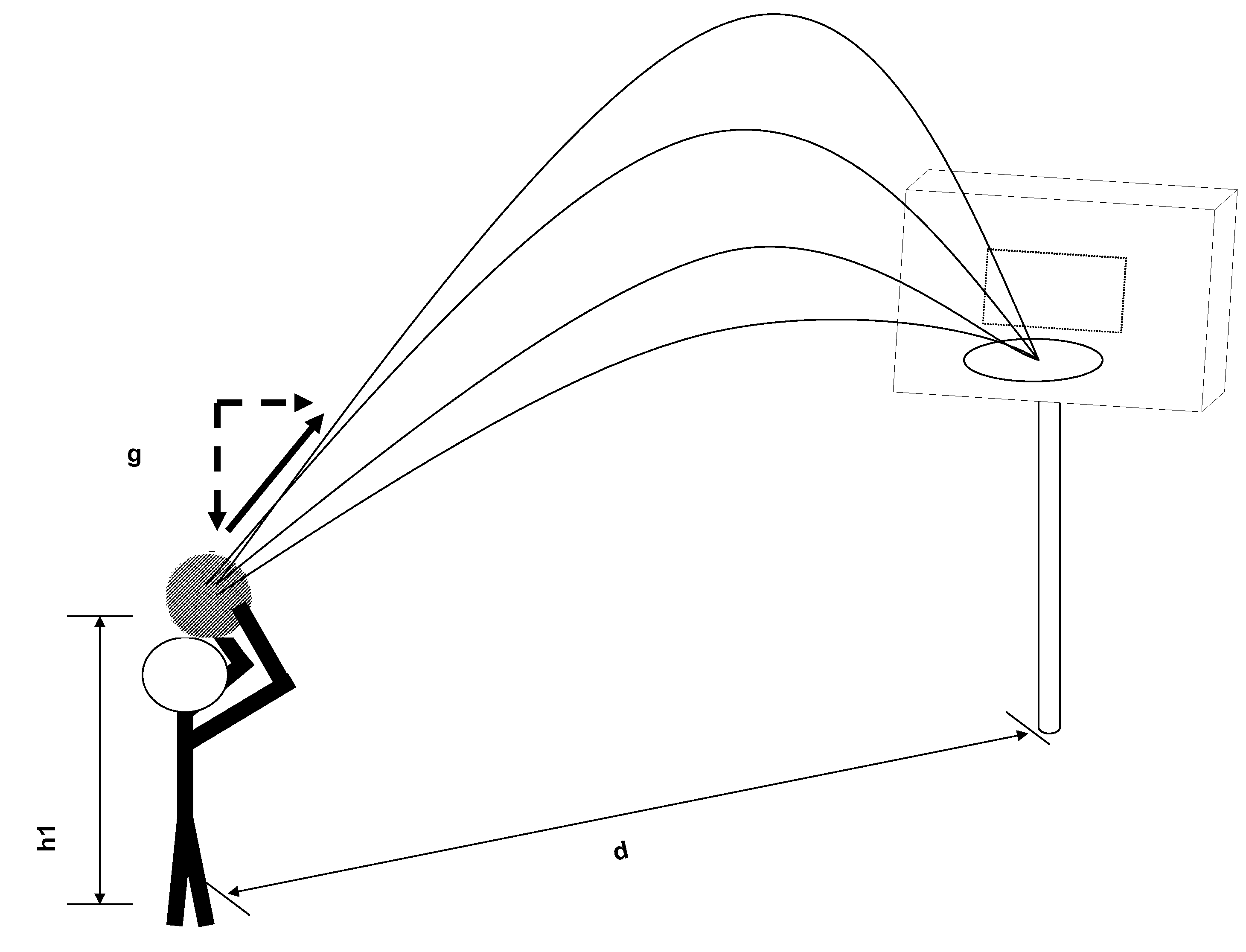
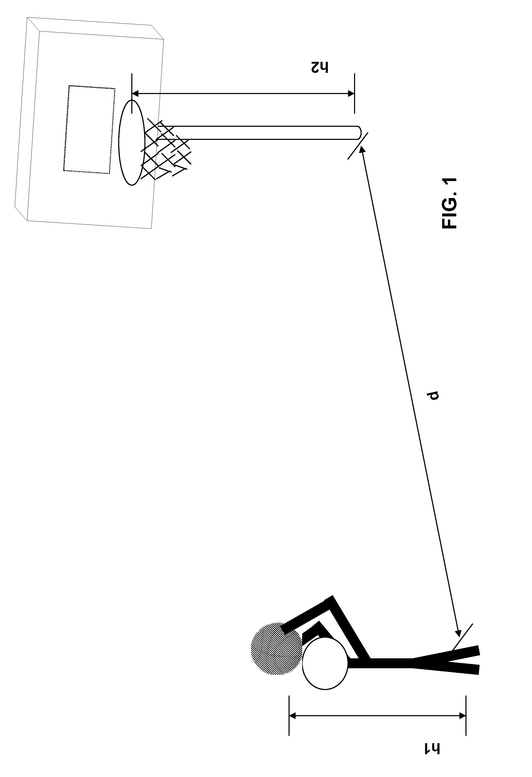
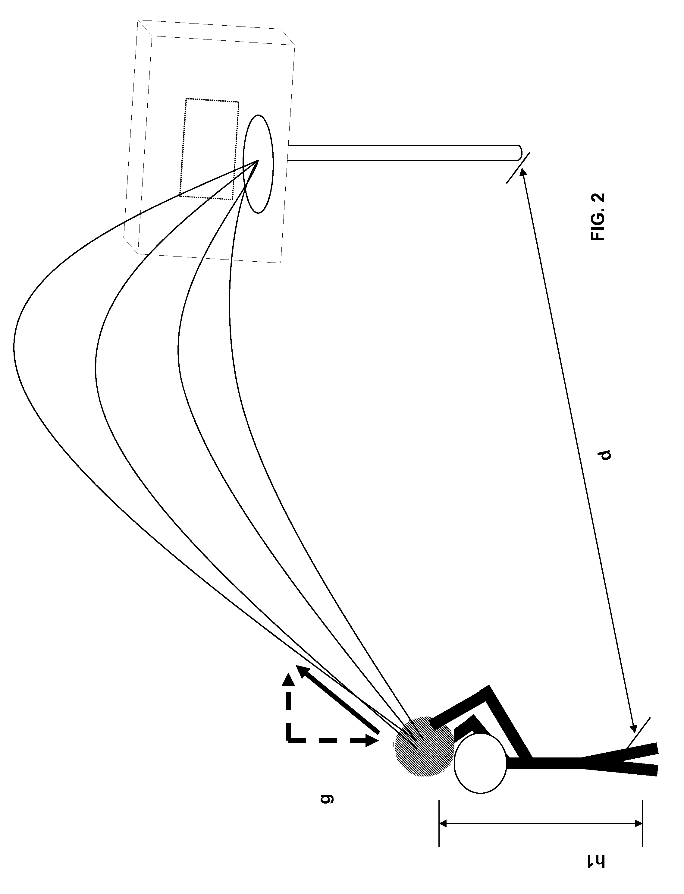
[0007]Accordingly, there is a need for a basketball that could provide information to prospective players about the nature of their shooting—specifically, the velocity and angle of each shot. The present invention fulfills this need by incorporating a thee-axis accelerometer, a transceiver and a microcontroller, of the type known as the ZSTAR and manufactured by Freescale Semiconductor and described in a publication entitled Wireless Sensing Triple Axis Reference Design Designer Reference Manual. During operation, the ball's accelerometer senses acceleration and then uses the microcontroller to integrate the area under the acceleration curve. It therefore calculates velocity and then employs the transceiver to send the output to a nearby laptop computer to display the results. By understanding how an accelerometer is oriented inside the basketball, we can determine the initial release angle. Using software to extract the acceleration due to motion, we can integrate the acceleration values to approximate velocity.With the use of these three components, the basketball can help a player improve their shot by providing feedback information on the velocity and angle of their shooting.

Problems solved by technology

It is difficult to think of a performance statistic in any other sport that has shown no improvement in the last 45 years.
Most shots miss because they are too short or too long.
Distance of a shot is controlled by arc and shooters at all levels have great difficulty controlling the arc of their shots.
However, knowing the proper angle and release velocity needed is only half of the story.
Such systems, however, are expensive, cumbersome, and do not provide immediate feedback to the shooter.

Method used


Image

  • Intelligent basketball
  • Intelligent basketball
  • Intelligent basketball

Examples


Embodiment Construction

[0022]The present invention comprises a device for providing information concerning position and movement of a sports implement, preferably a basketball to a user. As shown in FIG. 3, the device generally comprises a basketball 10, a sensor board 20, a receiver board 30, and a personal computer 40.

[0023]The basketball 10 has an opening 12 therein for fixedly receiving a rigid cylinder 14. The rigid cylinder 14 is fixed in position within the basketball by means such as flange 16. The specifics of the connection between the rigid cylinder 14 and basketball 10 are more fully described in United States Patent Application Publication No. US2002 / 0187866 A1, the subject matter of which is hereby incorporated by reference for descriptive purposes, but which does not constitute the present invention. The rigid cylinder has a open end at the surface of the basketball and a closed end inside the basketball. A cap 18 is provided to selectively cover the open end of the rigid cylinder. Accordin...


PUM


Abstract

A device for providing information concerning position and movement of a ball, in particular a basketball, to a user is provided. The device includes a ball having an opening therein. A sensor board is positioned within the opening in the ball. The sensor board carries a three-axis accelerometer electrically connected to a microcontroller and a transceiver. A receiver board is also provided and is located remotely from the ball. The receiver board carries a transceiver electrically connected to a microcontroller and a plug for connecting to a personal computer. The accelerometer on the sensor board continuously senses the position and acceleration of the ball. That information is then transmitted wirelessly to the receiving board by the transceivers. The position and acceleration information is then integrated in order to calculate the end position of the ball based on the position and acceleration information and previously input data on the shooter's height, distance from the basket and height of the basket. The data is then transferred to a personal computer by a USB connection for display to the shooter.

Description

FIELD OF THE INVENTION[0001]The invention relates to a sports implement such as a ball, preferably a basketball, that provides information to a basketball player about the nature of his or her shot, specifically, the velocity and angle of each shot.BACKGROUND OF THE INVENTION[0002]Basketball shooting percentages have been flat or decreasing at all levels of competition. For example, the National Basketball Association average free throw shooting percentage has been constant at around 74% since 1958. Nearly one-third of all NBA players shoot less than 70% from the free throw line. It is difficult to think of a performance statistic in any other sport that has shown no improvement in the last 45 years.[0003]Most shots miss because they are too short or too long. Distance of a shot is controlled by arc and shooters at all levels have great difficulty controlling the arc of their shots. Arc is the path the basketball flies from the time it leaves the shooter's hand until it arrives at t...

Claims


Application Information

Patent Timeline
IPC IPC(8): A63B43/00G06F19/00
CPCA63B43/00A63B2220/12A63B2243/0037A63B2225/50A63B2220/40
Inventor GOLD, ROBERT S.
Owner GOLD ROBERT S
Learn More