Posterior Dynamic Stabilization System With Flexible Ligament

a dynamic stabilization system and flexible technology, applied in the field of posterior dynamic stabilization system with flexible ligament, can solve the problems of further damage, disadvantageous caps, limited use of caps, etc., and achieve the effects of limiting undesirable excessive motion, restricting further flexion, and limiting flexion

Inactive Publication Date: 2009-12-31
DEPUY SYNTHES PROD INC
View PDF103 Cites 84 Cited by
  • Summary
  • Abstract
  • Description
  • Claims
  • Application Information

AI Technical Summary

Benefits of technology

[0022]The present invention can limit undesirable excessive motion by way of an elastomer or woven polymer ligament that changes shape to allow some flexion motion. With progressive flexion, the weave becomes tighter or looser and the elastomer stretches to restrict further flexion.
[0023]The present invention can limit flexion by providing a ligament (or sleeve) that has slack. The sleeve functions as an elongation stop which does not provide any stiffness in flexion.

Problems solved by technology

As a result, additional stress may be applied to the adjoining levels, thereby potentially leading to further damage.
Capping techniques, however, are limited in use as they will not remove the source of the pain in osteoarthritic joints.
Caps are also disadvantageous as they must be available in a variety of sizes and shapes to accommodate the wide variability in the anatomical morphology of the facets.
Caps also have a tendency to loosen over time, potentially resulting in additional damage to the joint and / or the bone support structure containing the cap.
One drawback of current articulating facet replacement devices, however, is that they require the facet joints to be resected.
Moreover, alignment of the articulating surfaces with one another can be challenging.

Method used


Image

  • Posterior Dynamic Stabilization System With Flexible Ligament
  • Posterior Dynamic Stabilization System With Flexible Ligament
  • Posterior Dynamic Stabilization System With Flexible Ligament

Examples


Embodiment Construction

[0028]Certain exemplary embodiments will now be described to provide an overall understanding of the principles of the structure, function, manufacture, and use of the devices and methods disclosed herein. One or more examples of these embodiments are illustrated in the accompanying drawings. Those skilled in the art will understand that the devices and methods specifically described herein and illustrated in the accompanying drawings are non-limiting exemplary embodiments and that the scope of the present invention is defined solely by the claims. The features illustrated or described in connection with one exemplary embodiment may be combined with the features of other embodiments. Such modifications and variations are intended to be included within the scope of the present invention.

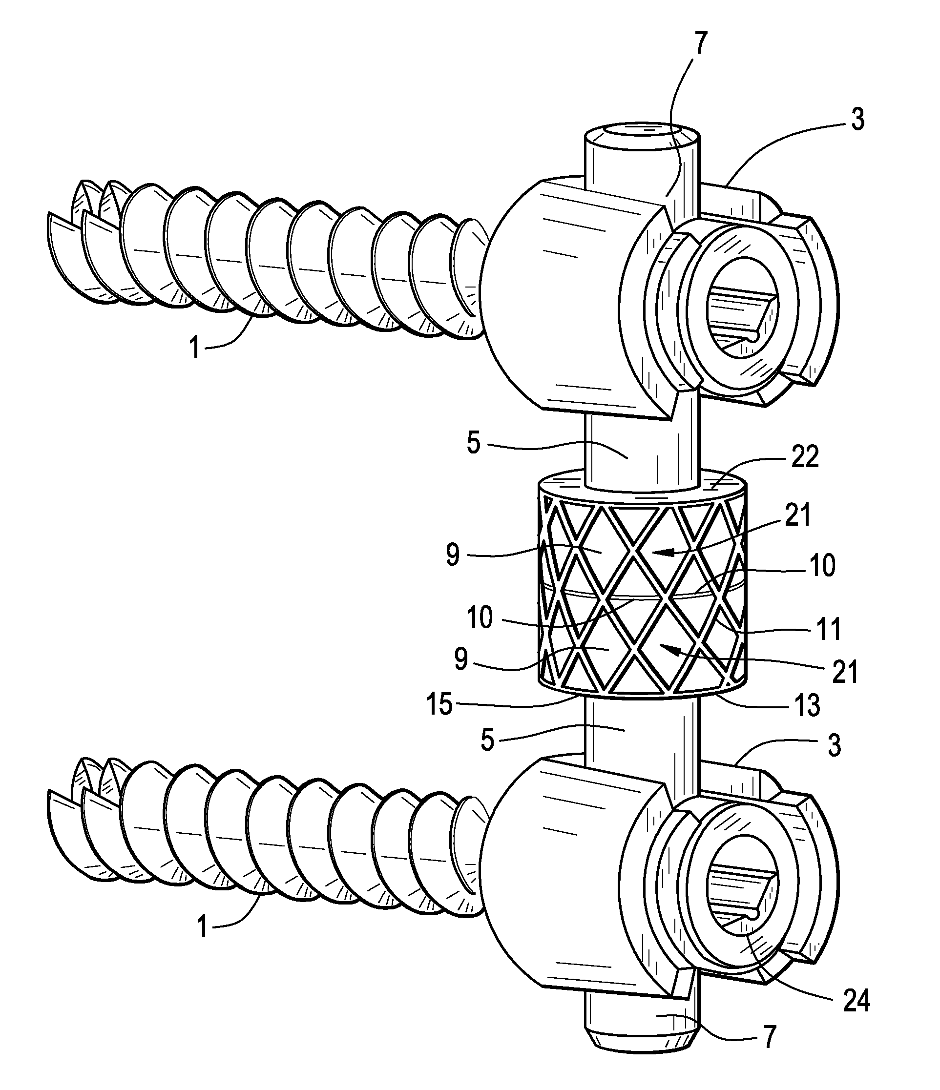
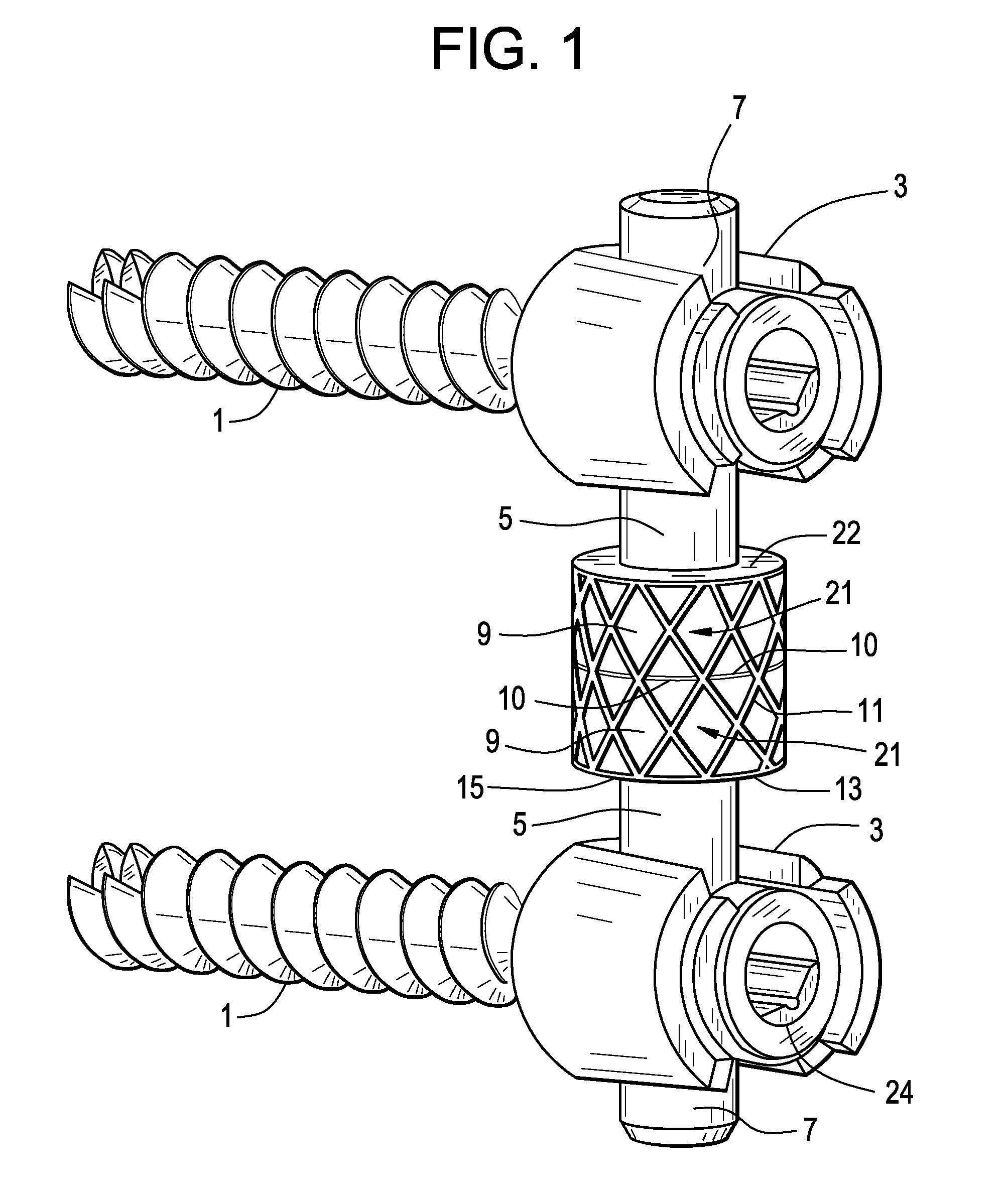
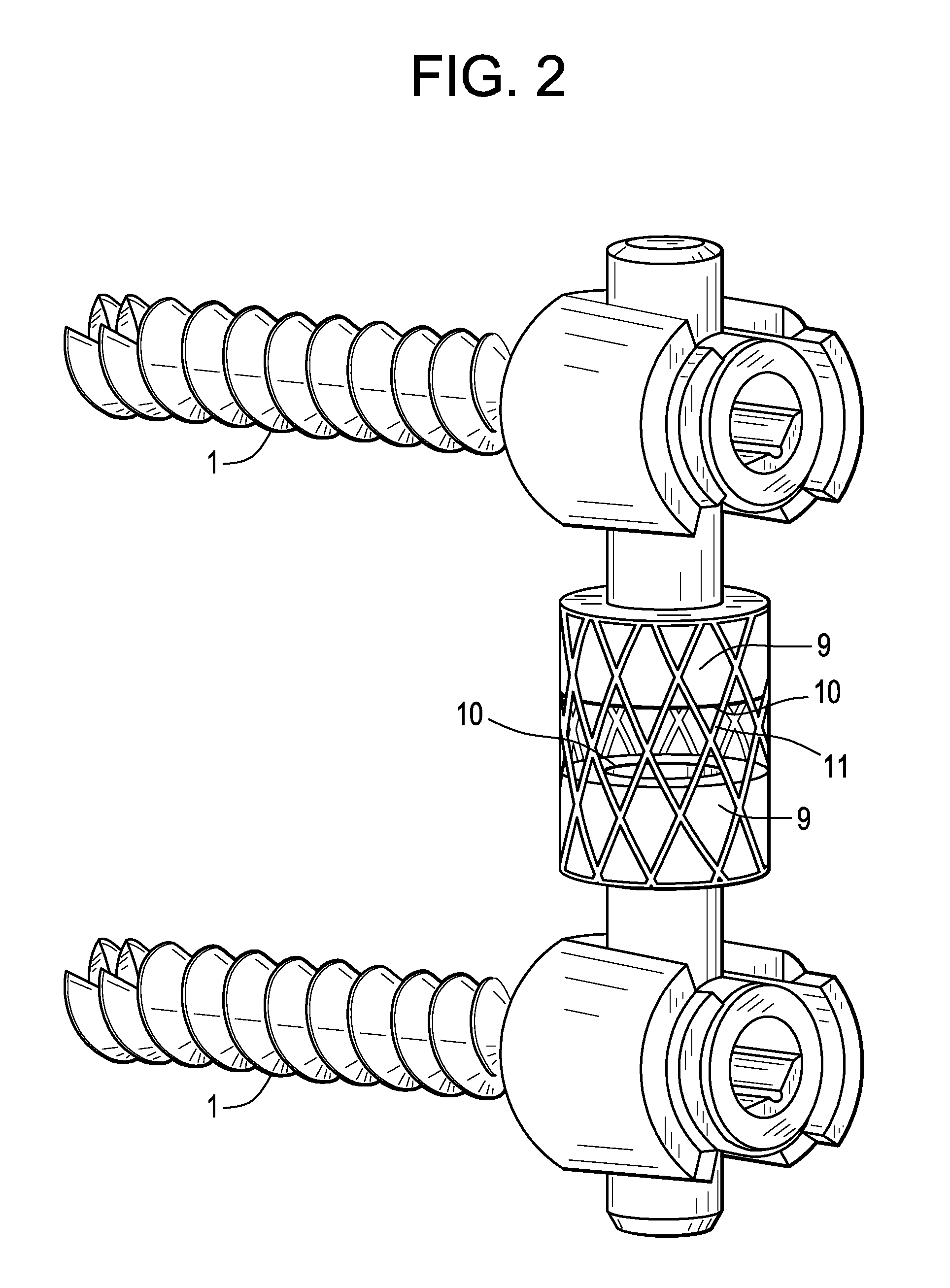
[0029]Now referring to FIG. 1, there is provided a posterior dynamic spinal stabilization system, comprising:[0030]a) first and second bone anchors 1, each anchor having a recess 3 for receiving a rod...


PUM


Abstract

A posterior dynamic spinal stabilization system having a sock or sleeve as the ligament to join a split rod so that during flexion, the ligament becomes taut to create an elongation limit, and during extreme extension, the upper and lower bumpers come together, thereby preventing further extension.

Description

BACKGROUND OF THE INVENTION[0001]The vertebrae in a patient's spinal column are linked to one another by the disc and the facet joints, which control movement of the vertebrae relative to one another. Each vertebra has a pair of articulating surfaces located on the left side, and a pair of articulating surfaces located on the right side, and each pair includes a superior articular surface, which faces upward, and an inferior articular surface, which faces downward. Together the superior and inferior articular surfaces of adjacent vertebra form a facet joint. Facet joints are synovial joints, which means that each joint is surrounded by a capsule of connective tissue and produces a fluid to nourish and lubricate the joint. The joint surfaces are coated with cartilage allowing the joints to move or articulate relative to one another.[0002]Diseased, degenerated, impaired, or otherwise painful facet joints and / or discs can require surgery to restore function to the three joint complex. ...

Claims


Application Information

Patent Timeline
Patent Type & Authority Applications(United States)
IPC IPC(8): A61B17/70A61B17/04
CPCA61B17/7004A61B17/7025A61B17/7022
Inventor MOUMENE, MISSOUMFANGER, JONATHANBARTISH, JR., CHARLES M
Owner DEPUY SYNTHES PROD INC
Why Eureka
Try Eureka